Dc power, Ac power (optional), Figure 9 transient protection module wiring – Detcon RD-64X-N7 User Manual
Page 11: 1 dc power, 2 ac power (optional)
RD-64X Operators Manual
3.2.1 DC Power
The RD-64X-N7 remote display is generally powered by a DC voltage source which is typically provided
by the controller it is interfaced with but can also be provided externally by the customer through another
voltage source. The remote display requires 11.5-30VDC to the PWR and GND terminals of connector J7.
A transient protection module is provided inside a condulet/J-Box
(See Figure 7) to protect the unit from
power spikes or overloading. It is strongly recommended to use the transient protection module if no
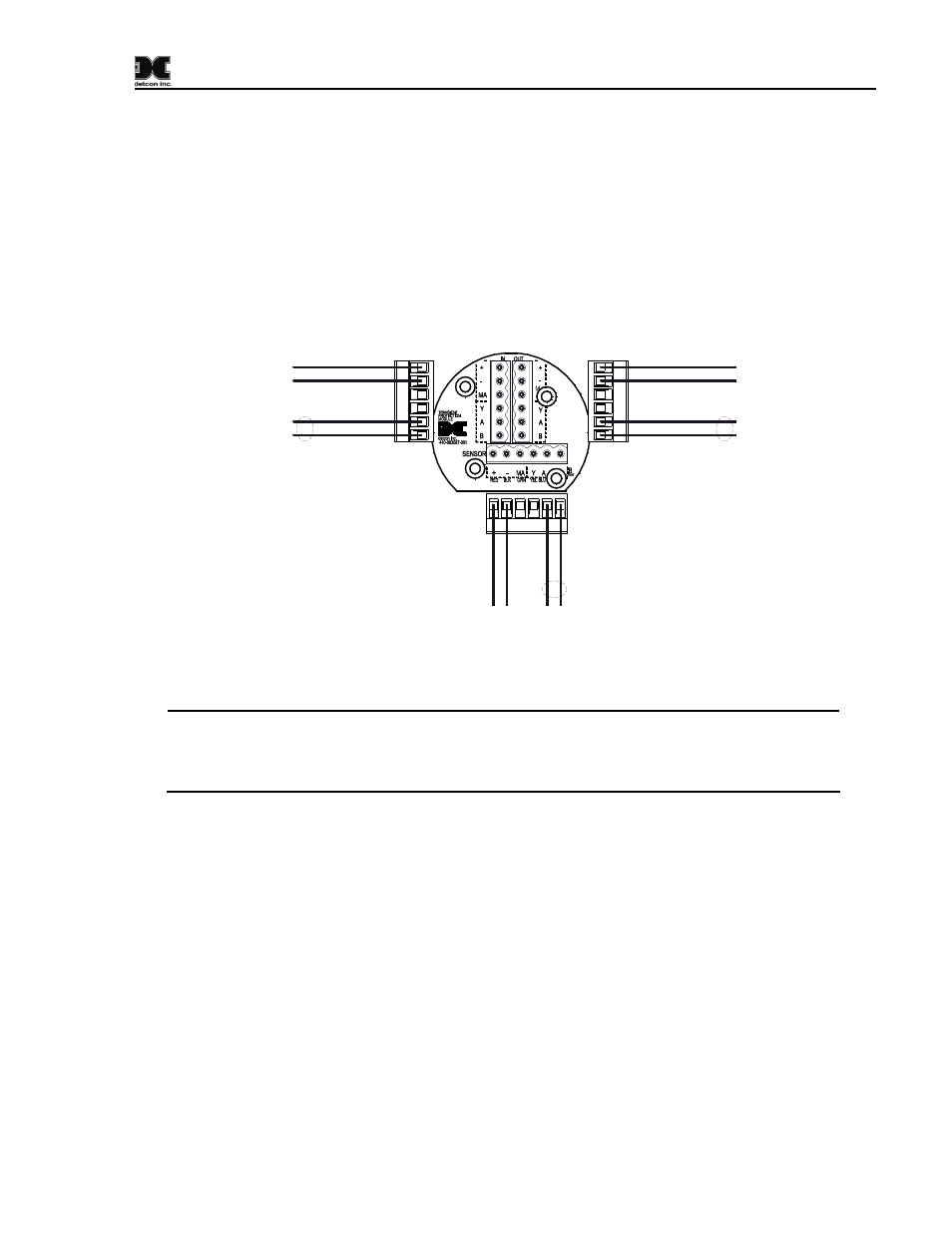
transient protection is provided by the controller or external voltage source. Refer to Figure 9 for wiring if
the transient protection module is used. Only one RL-4 relay output module can be supported by the
transient protection module. Additional RL-4s will need to be powered separately and have their own
separate transient protection.
PW
R (+
)
GND (-)
A1
(+
)
B1
(-)
VDC Power & Modbus RS-485 Out
to RD-64X-N7 Remote Display
J7 Connector
VDC Out (+)
VDC Out (-)
A (+) Modbus Out
B (-) Modbus Out
VDC In (+)
VDC In (-)
Modbus In A (+)
Modbus In B (-)
Modbus RS-485 Out
to RL-4 Module
Modbus RS-485 In
from Control Device
VDC Power Out
to RL-4 Module
VDC Power In from Control Device
or External Voltage Source
Figure 9 Transient Protection Module Wiring
NOTE: The supply of power should be from an isolated source with over-current protection.
The input voltage range must be between 11.5-30VDC. The power supply used for the RD-
64X-N7 remote display should have a common ground with the power supply used for the
controller.
3.2.2 AC Power (Optional)
The RD-64X-N7 remote display can also be AC powered using Detcon’s optional AC/DC converter
module which can be installed inside the condulet/J-Box in place of the transient protection module. This
module takes an input voltage of 90-264VAC at 50-60Hz and outputs 24VDC. Refer to Figure 10 for
wiring if the AC/DC converter module is used. This module is used to power the remote display only.
Any RL-4s will need to be powered separately with their own separate transient protection. Only the
Modbus™ interface can be shared with RL-4s in this configuration. Connections C and D are straight
through connections to be used as needed.
Model RD-64X Operators Manual
Rev. 0.1
Page 7 of 30