Modbus communications, Modbus register map, Figure 15 n7 remote switch input – Detcon RD-64X-N7 User Manual
Page 28: Table 2 rd-64x register map, 1 modbus register map
RD-64X Operators Manual
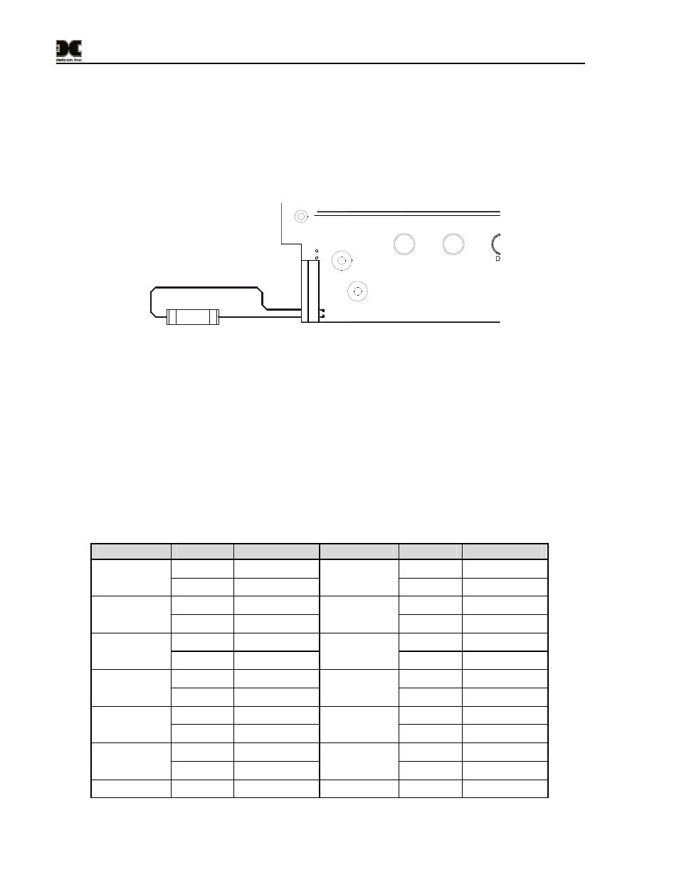
7.4 Optional Remote Alarm Reset/Acknowledge Switch (N7 Enclosure)
The RD-64X-N4X remote display comes with an external Remote Alarm Reset/Acknowledge switch
located on the side of the enclosure. The RD-64X-N7 remote display has the option of adding an external
Remote Alarm Reset/Acknowledge switch and will have to be mounted externally such as in the bottom of
a J-Box if one is available. The Reset Switch enables the user to reset or acknowledge alarms without
having to open the enclosure and should be a normally-open momentary contact push button type switch.
For the N7 enclosure, connect the switch to the terminals “SW” on connector J7 of the RD-64X PCA (See
Figure 15) Once installed, pushing the switch will execute the reset/acknowledge function.
RESET SWITCH
1
2
SW1
PWR
GND
A2
B2
A1
B1
SW
J7
D3
D4
Figure 15 N7 Remote Switch Input
8.
Modbus Communications
The RD-64X remote display features a Modbus™ compatible communications protocol and is addressable
by a PLC, PC/HMI, DCS or other Modbus™ RTU master-polling devices. Communication is
accomplished by two wire half duplex RS-485, 9600 baud, 8 data bits, 1 stop bit, no parity, through the
display’s primary port (COMM1).
8.1 Modbus Register Map
Table 2 RD-64X Register Map
Channel #
Register
Description
Channel #
Register
Description
40000 Reading
40064 Reading
Channel 1
40001 Status
Channel 33
40065 Status
40002 Reading
40066 Reading
Channel 2
40003 Status
Channel 34
40067 Status
40004 Reading
40068 Reading
Channel 3
40005 Status
Channel 35
40069 Status
40006 Reading
40070 Reading
Channel 4
40007 Status
Channel 36
40071 Status
40008 Reading
40072 Reading
Channel 5
40009 Status
Channel 37
40073 Status
40010 Reading
40074 Reading
Channel 6
40011 Status
Channel 38
40075 Status
Channel 7
40012 Reading Channel 39
40076 Reading
Model RD-64X Operators Manual
Rev. 0.1
Page 24 of 30