Modbus connections, Rl-4 alarm outputs, Rl4 relay outputs – Detcon RD-64X-N7 User Manual
Page 12: Figure 10 ac/dc converter module wiring, 1 rl4 relay outputs, 3 modbus connections
RD-64X Operators Manual
J3
N
L
E
+24V
GND
A
B
C
D
D
C
B
A
GND
+24V
J1
J2
U1
AC IN
+24VDC Power & Modbus RS-485
Out to RD-64X-N7 Remote Display
J7 Connector
VAC Power In from
External Voltage Source
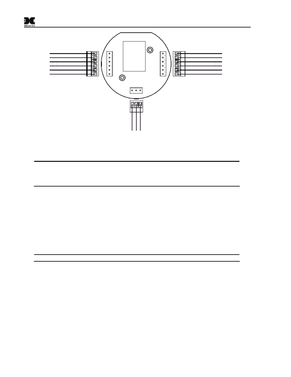
Note: If RL-4s are used,
connect the first RL-4's Modbus
interface in parallel to A (+) and
B (-) accordingly. RL-4s must
be powered separately.
Not Used
Not Used
Feed Thru Connection (C)
Feed Thru Connection (D)
Modbus In A (+)
Modbus In B (-)
Feed Thru Connection (D)
Feed Thru Connection (C)
GND (-)
PWR (+)
B1 (-)
A1 (+)
VAC
In
(N
)
VAC In
(
L)
GND
(E)
Modbus RS-485 In
from Controller/Out to RL-4s
Figure 10 AC/DC Converter Module Wiring
NOTE: The supply of power should be from an isolated source with over-current protection.
The input voltage range must be between 90-264VAC. The power supply used for the RD-
64X-N7 remote display should have a common ground with the power supply used for the
controller.
3.2.3 Modbus Connections
The serial RS-485 (Modbus™) connection from the monitored controller (Slave) to the RD-64X-N7 remote
display (COMM1 Master) is provided to the A1 and B1 terminals of connector J7. Refer to Figure 9 for
wiring if using the provided transient protection module or Figure 10 if using the optional AC/DC
converter module. The A2 and B2 terminals of connector J7 are used to connect to another remote display
where the RD-64X-N7 will be seen as a slave device. RS-485 connections require 24 AWG, two
conductor, shielded, twisted pair cable. Belden P/N 1502P is recommended for a single cable providing
serial communication and power. Belden P/N 9841 is recommended for a single cable providing serial
communication only.
NOTE: The RD-64X-N7 remote display and the controller should have a common ground.
4.
RL-4 Alarm Outputs
4.1 RL4 Relay Outputs
The RD-64X remote display features the capability of adding RL-4 alarm relay modules to control (fire)
annunciating devices near the remote display. There are four Form C, Single Pole Double Throw (SPDT),
5 Amp relay contacts in the RL-4 module. Each relay in the module is assigned specifically to one alarm.
Relay 1 is assigned to Alarm 1, relay 2 is assign to Alarm 2, relay 3 is assigned to Alarm 3 and relay 4 is
assigned to Fault. Connections to the relay contacts of the RL-4 module are shown in Figure 11 and are
labeled C (Common), NO (Normally Open) and NC (Normally Closed). Note that the 5 Amp rating of the
relay contact should not be exceeded.
Model RD-64X Operators Manual
Rev. 0.1
Page 8 of 30