System operation and configuration, Operator interface, Prog switch – Detcon RD-64X-N7 User Manual
Page 16: Up arrow switch, Down arrow switch, Figure 12 magnetic programming tool, 1 operator interface
RD-64X Operators Manual
7.
System Operation and Configuration
The setup of the RD-64X remote display is critical for proper operation. Modbus™ addresses must be
correct on all the devices connected to the controller before the controller will acknowledge them. The
number of channels being monitored from the controller must be entered into the remote display to allow it
to communicate with them. These same Modbus™ addresses and number of channels monitored need to
be configured and entered on the RD-64X remote display so that the information matches the controller.
This also applies to the configuration of alarms and relays from the remote display which need to match the
controller. Three basic areas need to be configured:
¾
The number of channels being monitored must be determined before setup begins.
¾
Channel information should be configured to match the controller.
¾
Relay outputs must be configured to match the controller.
7.1 Operator Interface
The operator interface of the RD-64X remote display is accomplished via four internal magnetic switches
located above its backlit LCD display. The four switches offer a non-intrusive interface and allow for
complete configuration of the unit. These switches are labeled: PROG, “u” (Up Arrow), “v” (Down
Arrow) and ENTER. The ENTER switch also doubles as a RESET/ACK switch when on the main page
only (Not in Menu Mode). With reference to the Menu Flow Chart (See Figure 14), it is easy to learn how
to navigate the menus and make changes.
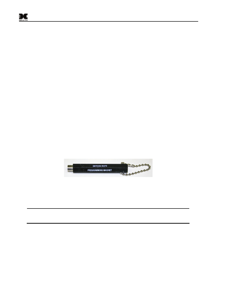
The magnetic programming tool (See Figure 12) is used to operate the magnetic switches. Switch action is
defined as a momentary contact (hold) on a switch marker (
⊗). For momentary contact, the programming
magnet is briefly held on the switch marker (
⊗) and then removed. This action will be referred to as a
“swipe” for the remainder of this manual.
Figure 12 Magnetic Programming Tool
7.1.1 PROG Switch
From the Main Display, the PROG switch enters into the Main Menu. Once inside the Main Menu, the
PROG switch acts as an “Escape” switch that moves backwards in the menu flow chart.
NOTE: While in Menu Mode there are no updates to gas readings on the remote display and
no alarms configured to the remote display will be triggered. Only gas readings on the
controller will be updated and alarms configured to the controller can potentially be triggered.
7.1.2 “u” Up Arrow Switch
This switch moves the user up the Main Menu flow chart. It is also used to change selected entries
within menu selections in the upward direction.
7.1.3 “v” Down Arrow Switch
This switch moves the user down the Main Menu flow chart. It is also used to change selected entries
within menu selections in the downward direction.
Model RD-64X Operators Manual
Rev. 0.1
Page 12 of 30