Power and modbus connections, Figure 8 rd-64x remote display pca, 2 power and modbus connections – Detcon RD-64X-N7 User Manual
Page 10
RD-64X Operators Manual
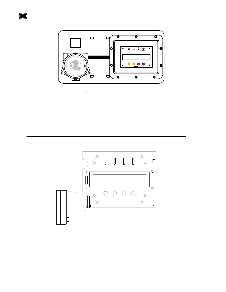
Mounting Plate
J-Box w/ Transient
Protection Module
RD-64X-N7
Place Spacers between N7 Enclosure
and Mounting Plate.
If an Alarm reset switch is installed, the switch should
be mounted in the bottom port of the J-Box.
If no reset switch is installed, install a
3
4
" NPT Plug.
MODEL RD-64X-N7
Remote Display
Figure 7 RD-64X Remote Display Assembly w/Mounting Plate
3.2 Power and Modbus Connections
Power and Modbus™ connections to the RD-64X-N7 remote display are made on connector J7 of its PCA
(Printed Circuit Assembly). A plug-in male connector is provided for input wiring terminations. This
connector style provides for quick disconnect convenience during replacement or servicing. To access
connector J7, remove the faceplate from the remote display enclosure to reveal the PCA.
NOTE: The J7 connector is located on top side of the PCA for the RD-64X-N7 and on the
bottom side of the PCA for the RD-64X-N4X.
R8
SW1
SW2
SW3
SW4
D3
D4
D5
D6
MA
IN
SECONDA
RY
1
1
J2
J6
J5
1
J7
PWR
GND
A1
B1
SW
A2
B2
J7
PWR
GND
A1
B1
SW
A2
B2
Figure 8 RD-64X Remote Display PCA
PWR/GND: DC power connection to power RD-64X-N7 remote display
A1/B1:
Primary Modbus™ connection (COMM1 Master) from controller (Slave) being monitored
A2/B2:
Secondary Modbus™ connection (COMM2 Slave) to another remote display
SW:
External switch connection for RESET/ACK function (Normally Open)
Model RD-64X Operators Manual
Rev. 0.1
Page 6 of 30