Dc power, Modbus connections, Figure 2 ac/dc inputs – Detcon RD-64X-N7 User Manual
Page 7: Figure 3 rs-485 connections, 2 dc power, 3 modbus connections
RD-64X Operators Manual
O
I
1A
O
I
1A
O
I
1A
24V
DC
GR
OUND
VA
C (
L1
)
NE
U
(
L2
)
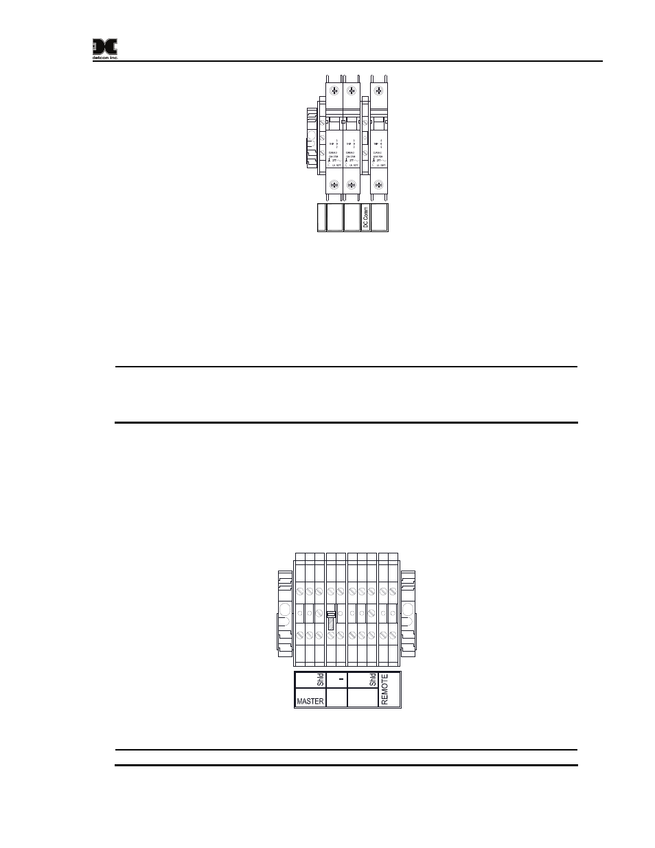
Figure 2 AC/DC Inputs
2.2.2 DC Power
For optional external DC power input, connect 11.5-30VDC to the terminals of the DIN rail mounted
terminal block labeled “24VDC” and “DC Comm” (See Figure 2). This input can be used for primary
power or back-up power in the event of an AC power failure. The DC input voltage source should be
capable of delivering at least .75 Amps of current to the load (18 Watts @ 24VDC) which will power up to
four RL-4 relay output modules.
NOTE: The supply of power should be from an isolated source with over-current protection.
The input voltage range must be between 11.5-30VDC. The power supply used for the RD-
64X-N4X remote display should have a common ground with the power supply used for
the controller.
2.2.3 Modbus Connections
The serial RS-485 (Modbus™) connection from the controller (Slave) being monitored to the RD-64X-
N4X remote display (COMM1 Master) is provided to the terminals of the DIN rail mounted terminal block
labeled “RS-485 MASTER” (See Figure 3). The serial RS-485 connection labeled “RS-485 SLAVE” is
used to connect to another remote display where the RD-64X-N4X will be seen as a slave device in that
specific Modbus™ loop. RS-485 connections require 24 AWG, two conductor, shielded, twisted pair
cable. Belden P/N 9841 is recommended for a single cable providing serial communication only.
RS-485
SLAVE
A B
RS-485 VDC
Out
+
RESET
A B
Figure 3 RS-485 Connections
NOTE: The RD-64X-N4X remote display and the controller should have a common ground.
Model RD-64X Operators Manual
Rev. 0.1
Page 3 of 30