Frequency output programming, Gate time filter, Mx 9000 process monitor – AW Gear Meters MX 9000 User Manual
Page 31
MX 9000 Process Monitor
Operation and Programming Manual
30
MX 9000 User Manual, Rev. 2.0 7/16/2013
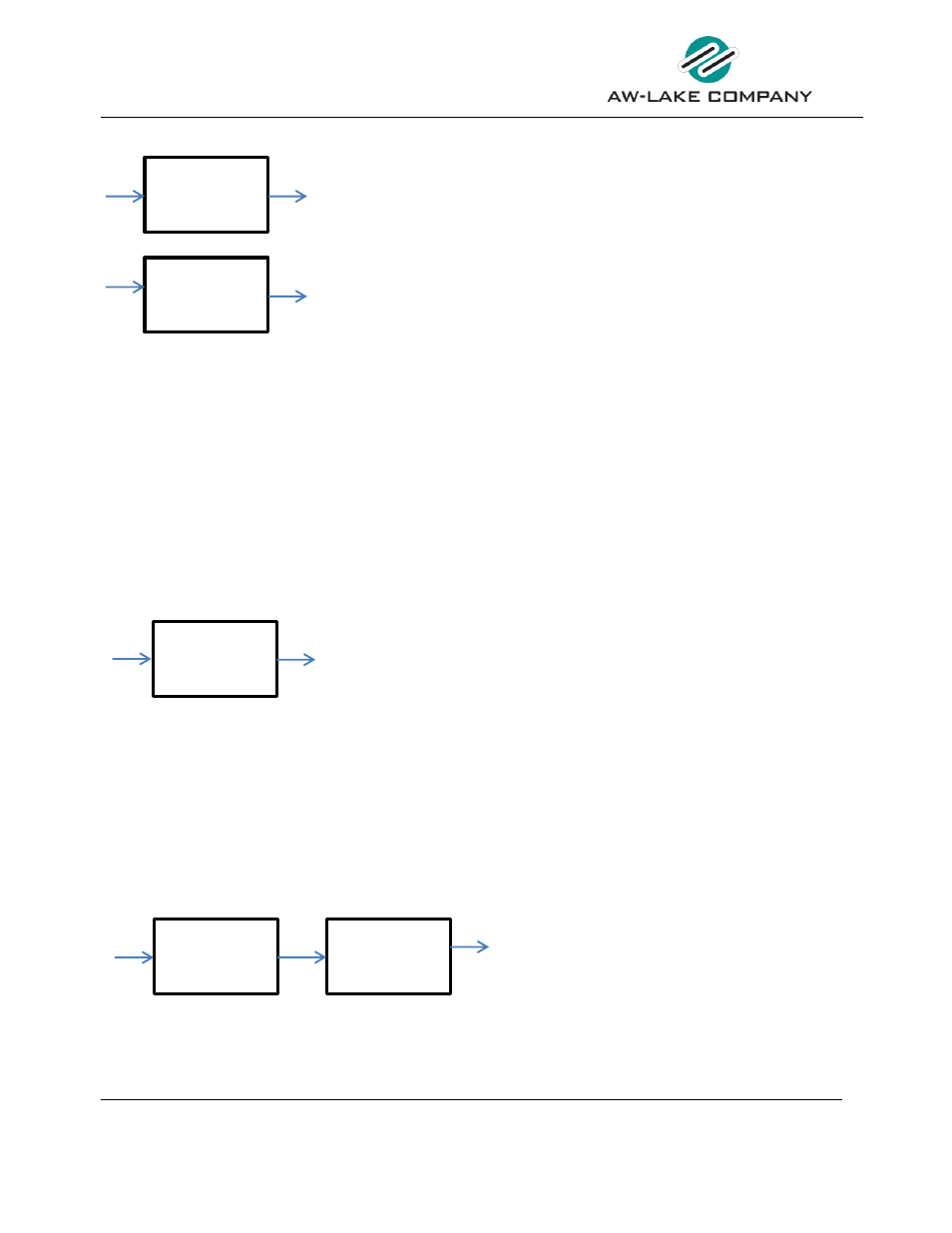
TOTAL & GRAND TOTAL Limits
Select Limit Screen
Select Limit Screen
Figure 21: Total and Grand Total Limits
TOTAL / GRAND TOTAL Value
Enter the Total or Grand Total value at which the respective Limit output should change state. When
the Total or Grand Total is reset to zero, the limit pin changes back to initial state.
WARNING / ALARM AB / BA Value
The Warning or Alarm AB / BA limit will activate the selected relay when the respective limit is reached
in the Ratio AB and BA menus. Select the Warning or Alarm trigger desired and set the values in the
Ratio menus starting on page 35.
Frequency output programming
Select Limit Screen
Figure 22: Frequency Output Programming
The third output can only be set to output the incoming frequency from one of the two inputs. From
the top Limit programming menu, choose the Frequency Output option, press
ENTER
and use the
UP
or
DOWN
button to select the input channel to route to the frequency output. There are no other
variables to program. The output frequency is not affected by the Gate Time filter and cannot be
linearized. It is always the raw incoming frequency from the selected sensor.
Gate Time Filter
Linearizer Menu
Figure 23: Gate Time Filter
Tota l Value
0001000.00 GAL
Gra nd Total Value
0010000.00 GAL
Sel ect Li mit
Frequency Out
Sel ect Li mit Type
> Si gnal A
Ga te Time Filter A
(i n seconds)
001.0
Ga te Time Filter B
(i n seconds)
001.0