Technical data, Power supply, Flow sensor power output – AW Gear Meters MX 9000 User Manual
Page 11: Frequency inputs, Analog output(s) 4-20 ma, Relay contact ratings, Mx 9000 process monitor
MX 9000 Process Monitor
Operation and Programming Manual
10
MX 9000 User Manual, Rev. 2.0 7/16/2013
Technical Data
Minimum Power Supply Requirements
16 VAC/250mA with supplied 110 VAC transformer, or
18-24 VDC/250mA. (customer supplied direct current)
120/240 VAC with option board 2
Flow Sensor Power Output
(2) @ 15 VDC/50 mA. each
Frequency Inputs
0-4.5 KHz, sine, square or saw-tooth; 5 volts minimum amplitude; 3.3K Ohm impedance
Analog Output(s) 4-20 mA
external-powered loop output into a maximum 500 Ohm load impedance with 24 volt supply
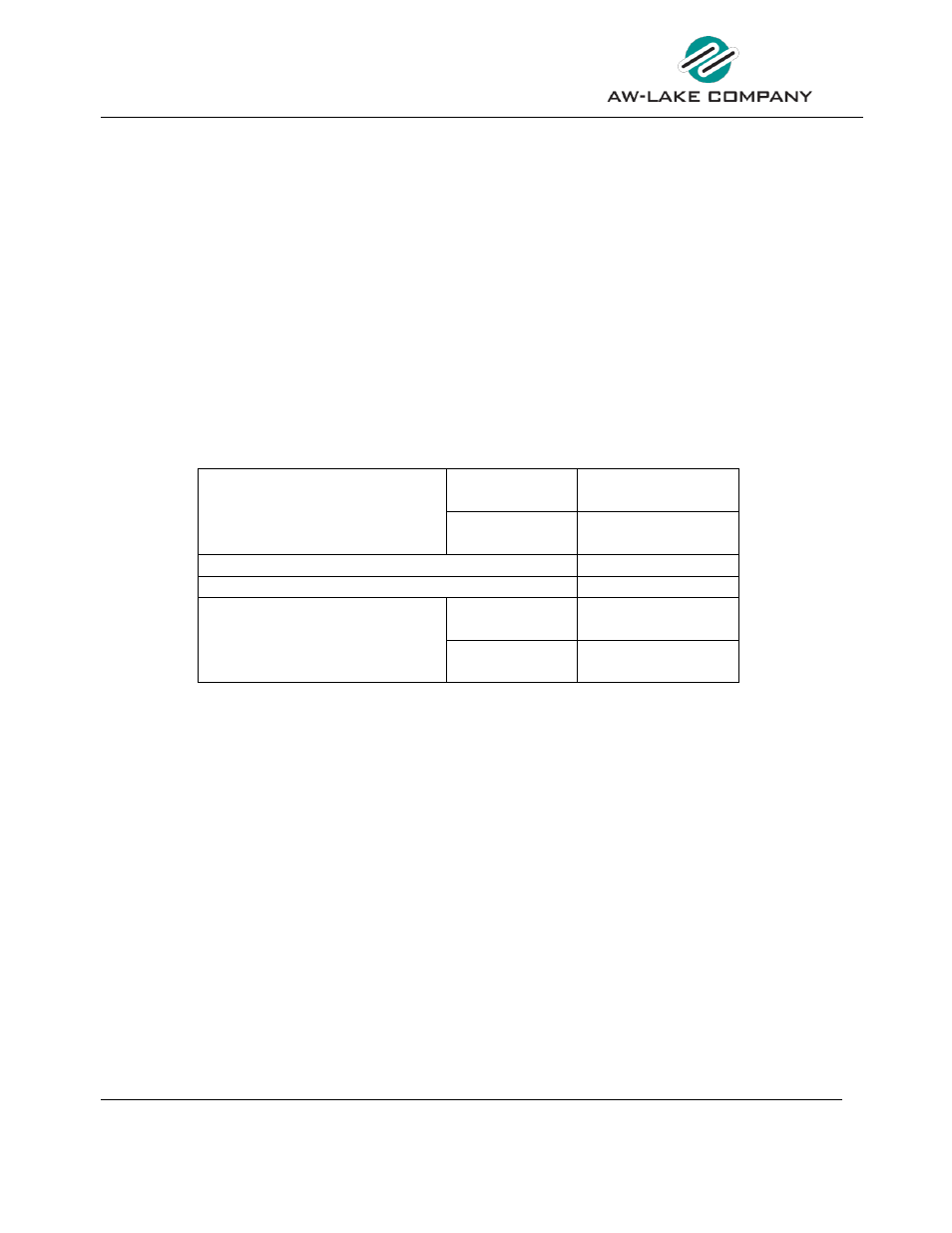
Relay Contact Ratings
Maximum
Switched
Power
Resistive Load
DC: 60W
AC: 125VA
Inductive Load
DC: 30W
AC: 60VA
Maximum Switched Voltage
100VDC, 250VAC
Maximum Switched Current
2A/DC, 1A/AC
Rated
Load
Resistive Load
DC: 30V, 2A
AC: 125V, 1A
Inductive Load
DC: 30V, 1A
AC: 125V, 0.3A
Figure 1: Relay Contact Ratings
NOTE: Maximum wire gauge 16 AWG
LOWER TERMINAL BLOCK CONNECTIONS:
Pin 1:
(+) 18-24 VDC Supply Voltage / 16 VAC Input
Pin 2:
(-) 18-24 VDC Supply Voltage Ground / 16 VAC Input
Pin 3:
(+) Sensor 1 Supply Voltage 15 VDC 25 mA MAX
Pin 4:
Sensor 1 Signal Input
Pin 5:
(-) Sensor 1 Supply / Signal Common
Pin 6:
(+) Sensor 2 Supply Voltage 15 VDC 25 mA MAX
Pin 7:
Sensor 2 Signal Input Housing Ground
Pin 8:
(-) Sensor 2 Supply / Signal Common
Pin 9:
(+) External Reset Input
Pin 10:
(-) External Reset Input
Pin 11:
(+) mA Loop 1 Output Limit 1
Pin 12:
(-) mA Loop 1 Output Limit 1