Introduction, Farm hand vent master 24 – Hired-Hand Farm Hand Series: Vent Master 24 User Manual
Page 4
Part No. 4801-5124 rev 10-03
Farm Hand Vent Master 24
2
4. Introduction
There is currently one model of the Vent Master 24 controller and it is used exclusively with the Farm
Hand SCS™ 24 Smart Control System:
(1)
Farm Hand Vent Master 24 without Variable Speed
The Farm Hand Vent Master 24 Stage Controller is designed to be one of the simplest controllers on
the market to operate, but to also be one of the most powerful. The Vent Master 24 combines the
features of the Farm Hand Stage Master 12 with the capabilities of the Farm Hand Power Vent into a
single controller. The Vent Master 24 works in combination with the Farm Hand SCS™ Panel by
communicating over the Local Network connection.
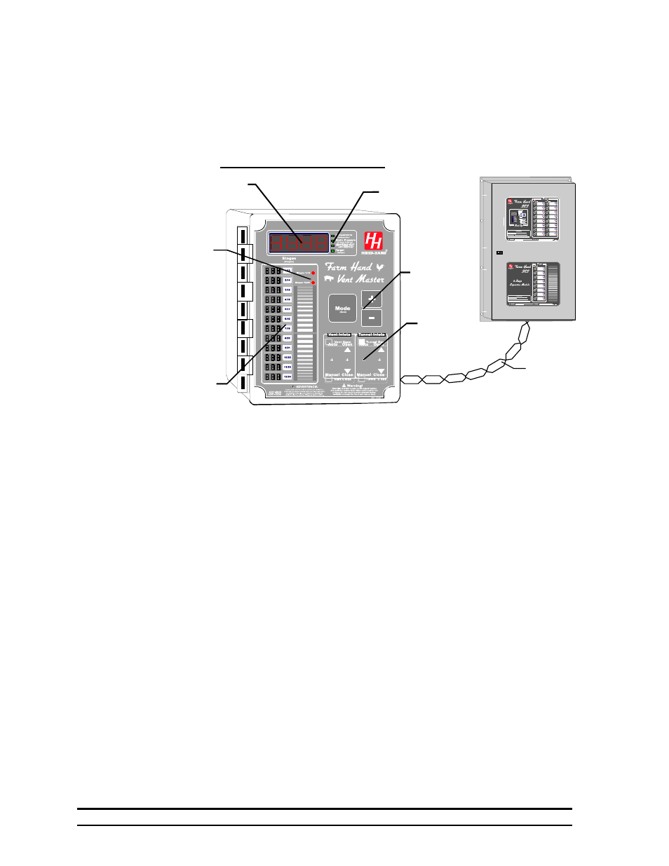
The Vent Master 24 has four main regions on the faceplate: the main display, stage displays, the
control button region and the vent machine control region. The main display area includes the main
display, and four green LED’s which tell what the main display is indicating. If the green light beside
“Temperature” is lit, then the display is showing the display option chosen in the Program Mode under
the parameter PSd. Refer to Section 6.1 for an explanation of the PSd parameter.
On the left hand side of the controller face are the stage displays. When the controller is operating, the
OnPoint of each stage (the temperature the stage will turn on) is displayed. Next to the stage indicators,
is a button imprinted with the number of the stage. Press this button to set the On and OffPoints for that
stage. (Stage OnPoints and OffPoints are discussed later in the manual.) Near the top of the Stage
Status indicators are two red LEDs that indicate which bank of Stages is being indicated in the Stage
Status indicators. The upper Led is On for Stages 1 through12 and the bottom LED is on for Stages 13-
24.
Just below the main display on the right hand side of the controller is the control button region. This
region has three buttons: Mode, Plus (+), and Minus (-). You will learn the use of these three buttons
later in this manual.
Finally, on the bottom right hand side of the controller is the Inlet machine control region. This region
includes an Automatic/Manual switch and an Open/Off/Close switch for the Tunnel Inlet machine and
the Vent Inlet machine.
Farm Hand Vent Master 24
Main Display
Control Buttons
Display Indicators
Vent Machine Controls
Stage Buttons
Stage Bank Indicators
Local
Network
Connection
SCS™ w/Back-Up