Warning, Maintenance, Wiring diagrams, schematics, etc – Hired-Hand Farm Hand Series: Vent Master 24 User Manual
Page 19
Part No. 4801-5124 rev 10-03
Farm Hand Vent Master 24
17
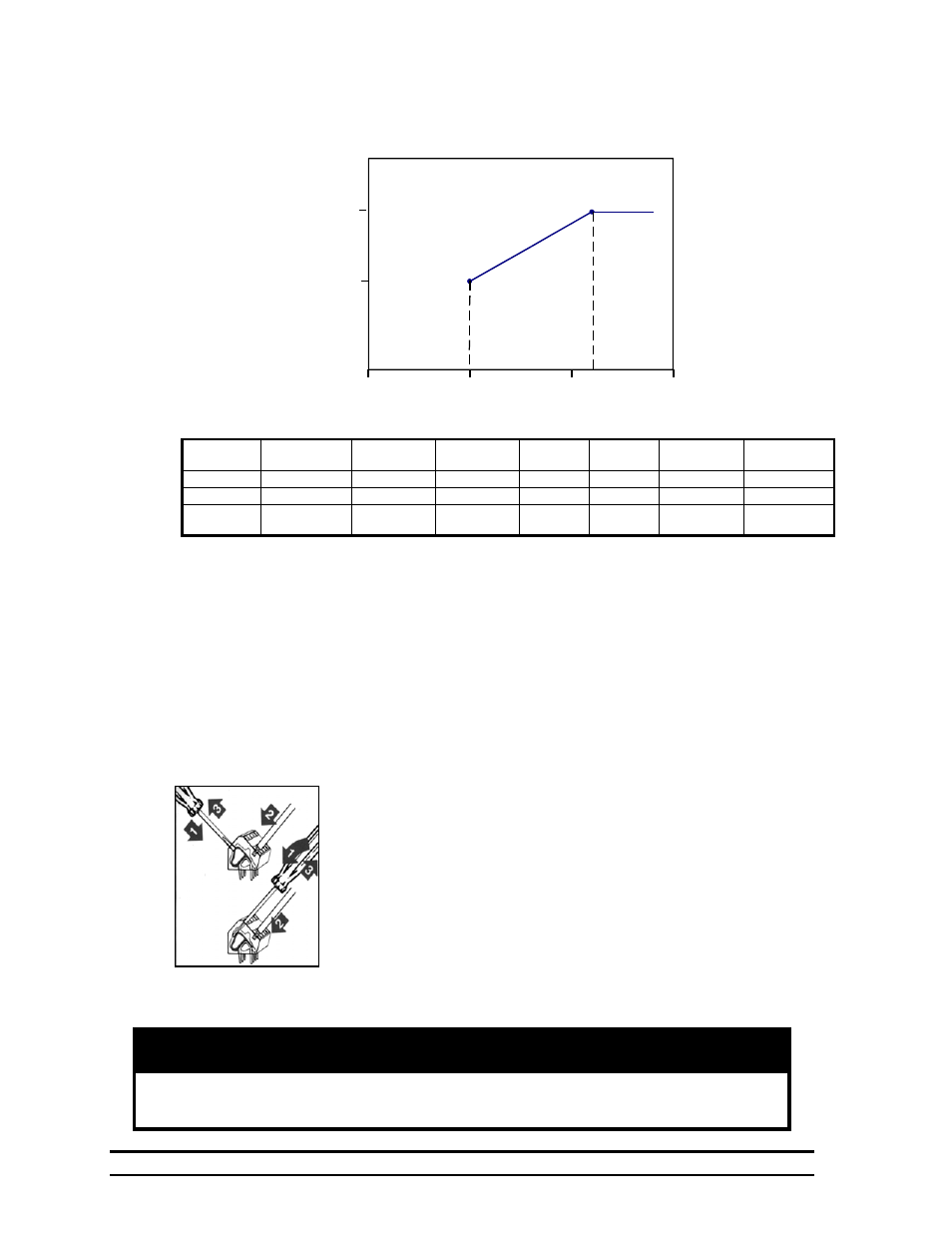
Table 1 Example Of Cool Timer Stage Operation
Brief Description Of Cool Timer Stage Operation
As you can see, a stage will be placed on the system timer once the temperature rises above
80ºF (OFF) and will start running 50% (P71) of the time. If the temperature continues to
increase then the run time percentage will also increase toward 90% (P70).
13. Maintenance
Check the calibration of your sensors at least once per quarter. You will need to have two people: one
person at the sensor with a trusted thermometer, and one at the controller to set the sensor to the proper
setting.
14. Wiring Diagrams, Schematics, etc.
All wiring connections for stages, vent machines, variable speed fans, and
curtain sensors inside the controller are made without terminals on the end
of the wire. To make the connection, strip about ¼” of the insulation off
the wire, and follow the diagram below.
1. Insert a small screwdriver into either the hole shown in the
diagram.
2. Insert the stripped end of the wire into the hole shown in the
diagram.
3. Remove the screwdriver, and tug slightly on the wire to check that
it is snug.
Warning!
Do not connect more than 12 amps of load to any one stage. The Variable
Speed Circuit will carry up to 12 amps.
Setting
Stage Sensor
Stage Mode
Stage Timer
OffPoint
OnPoint
Cool Timer
Max %
Cool Timer
Min %
Parameter
P1 P2 P3 OFF ON P70 P71
Value
10 02 02 80
86
90 50
Option
Sensor 1
Cool Stir
Timer ON
Minimum
OnPoint
Maximum
OnPoint
Maximum
Runtime %
Minimum
Runtime %
75
80
85
90
Runtime Percentage
Graph 1 ON/Off Stages
86ºF
OnPoint
90
50
80º F
OffPoint
Temperature (F)