Asante Technologies Intrachassis 9000 User Manual
Page 30
Installation and Set-up
Page 2-10
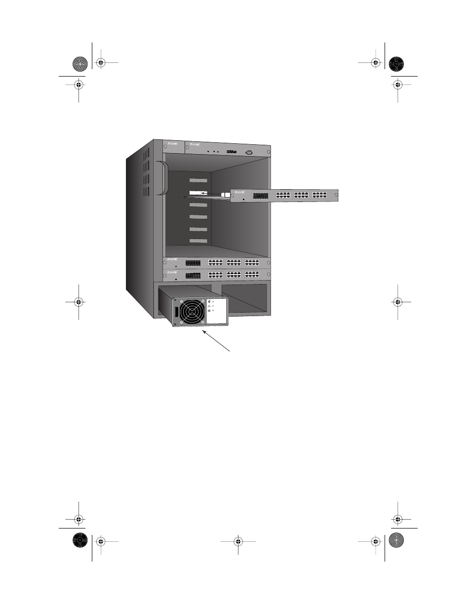
Figure 2-2 Installing module and power supply
4
Press both ejector levers in, toward the module’s face plate,
simultaneously. This will lock the module in place and
insure proper contact of all connecting surfaces.
5
Tighten the thumbscrews at the ends of the module’s face
plate, next to the ejector levers. Use a straight-bladed screw-
driver, so the thumbscrews cannot be loosened by hand.
Installation of the module is complete. Repeat this procedure for each module
you have purchased, then proceed to “Connecting Power”.
▲ Important: Modules are not to be removed from the Intra-
Chassis 9000 except by a qualified System Administrator.
!
Power
P-Fail
Fail
CM
IntraChassis 9000
24-port 10/100 Switch Blade
Power
1
3
5
7
9 11 13 15 17 19 21 23
2
4
6
8
10 12 14 16 18 20 22 24
Link/Speed
Duplex/Act
Link/Speed
Duplex/Act
7
5
3
1
8
6
4
2
15
13
11
9
16
14
12
10
23
21
19
17
24
22
20
18
IntraChassis 9000
24-port 10/100 Switch Blade
Power
1
3
5
7
9 11 13 15 17 19 21 23
2
4
6
8
10 12 14 16 18 20 22 24
Link/Speed
Duplex/Act
Link/Speed
Duplex/Act
7
5
3
1
8
6
4
2
15
13
11
9
16
14
12
10
23
21
19
17
24
22
20
18
Advanced Systems
Galaxy 9000 GigaSwitch
Power
Slot Control Center
1 2 3 4 5 6 7 8
Mode
Set
IntraChassis 9000
24-port 10/100 Switch Blade
Power
1
3
5
7
9 11 13 15 17 19 21 23
2
4
6
8
10 12 14 16 18 20 22 24
Link/Speed
Duplex/Act
Link/Speed
Duplex/Act
7
5
3
1
8
6
4
2
15
13
11
9
16
14
12
10
23
21
19
17
24
22
20
18
IntraChassis 9000
Management Engine
GLXY9.book Page 10 Thursday, February 17, 2000 3:04 PM