3 replacing ca3-blu12-01, 3 replacing ca3-blu12-01 -10 – Proface FP3900 - 19 Flat Panel" User Manual
Page 81
7.3 Backlight Replacement
FP-2500/FP-2600 Series User Manual
7-10
• Be sure not to pinch or cut any of the FP unit's internal wiring when
closing the case.
• If any of the attachment screws becomes misplaced, check to be sure
that they have not fallen inside the FP. If a screw has fallen inside the
FP, do not connect the unit’s power cord until it has been removed.
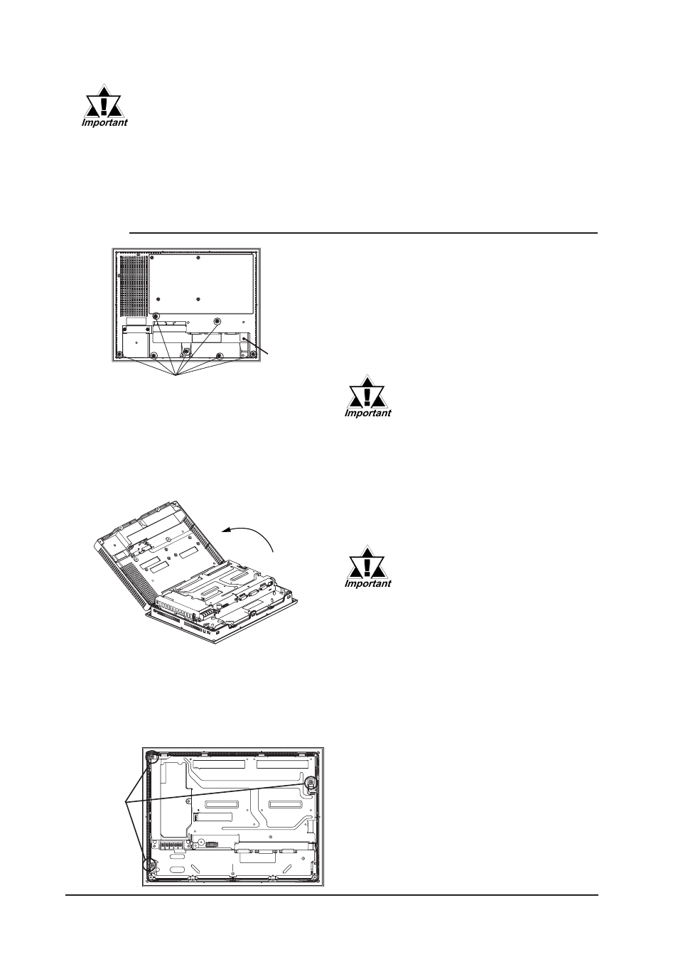
1) Turn the FP unit’s power OFF (i.e. dis-
connect the FP unit's power cord). Re-
move the three (3) I/F covers, and use
a Phillips screwdriver to remove the
case’s seven (7) rear attachment screws
and USB holder. Pivot the rear cover
open, starting from the top of the unit.
2) The cover is fastened at the bottom,
and hinges open.
3) Loosen the three (3) circuit board at-
tachment screws.
• Be sure not to break the rear
cover’s four (4) alignment
tabs when you open it.
• To prevent FP unit damage, be
sure the FP unit's rear cover
open/close direction is correct.
Since the attachment screws
are small, be sure not to lose
them or allow them to fall inside
the FP unit's case.
USB holder
Rear Attachment Screws
Attachment
Screws
7.3.3
Replacing CA3-BLU12-01