2 wiring, Connecting the power supply terminals – Proface FP3900 - 19 Flat Panel" User Manual
Page 44
FP-2500/FP-2600 Series User Manual
3-7
3.2 Wiring
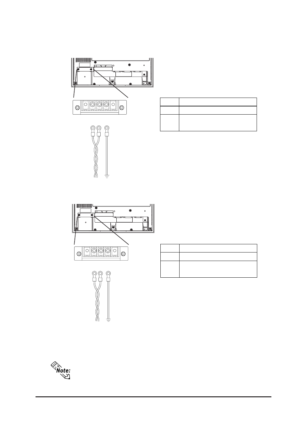
1) Confirm that that the FP unit's Power Cord is unplugged from the power supply.
2) Use a screwdriver to remove the Power Input Terminal Block's clear plastic cover.
3) Unscrew the screws from the middle three (3) terminals, align the Ring Terminals and
reattach the screws.
4) Replace the Power Input Terminal Block's clear plastic cover.
• Confirm that the ring terminal wires are connected correctly.
• A torque of only 0.5 to 0.6 N•m is required to tighten an attachment screw.
L
AC Input Live Line
N
AC Input Neutral Line
FG
Grounding Terminal connected to
the FP chassis.
Power
Terminal
Block
Connecting the Power Supply Terminals
FP2500-T12/FP2600-T12
+
Positive electrode
-
Negative electrode
FG
Grounding Terminal connected to
the FP chassis.
Power
Terminal
Block
FP2500-T42-24V/FP2600-T42-24V
L N FG
L N FG
+ - FG
+ - FG