3 rs-232c interface, 3 rs-232c interface -9, 3 interface specifications – Proface FP3900 - 19 Flat Panel" User Manual
Page 28: Rs-232c interface pin assignments and signal names
FP-2500/FP-2600 Series User Manual
2.3 Interface Specifications
2-9
Signal Names
Signal names used for the RS-232C Interface are designed to match the pin order
used on most PC RS-232C interfaces, which allows a straight cable to be used to
connect the two. Therefore, connect each pin's signal to the same signal name on
the PC side.
For example, the FP unit connector's pin #2 'RD' should be connected to the PC
connector's 'RD' terminal. For detailed signal direction information,
2.4 Cable Diagrams
2.3.3
RS-232C Interface
RS-232C Interface
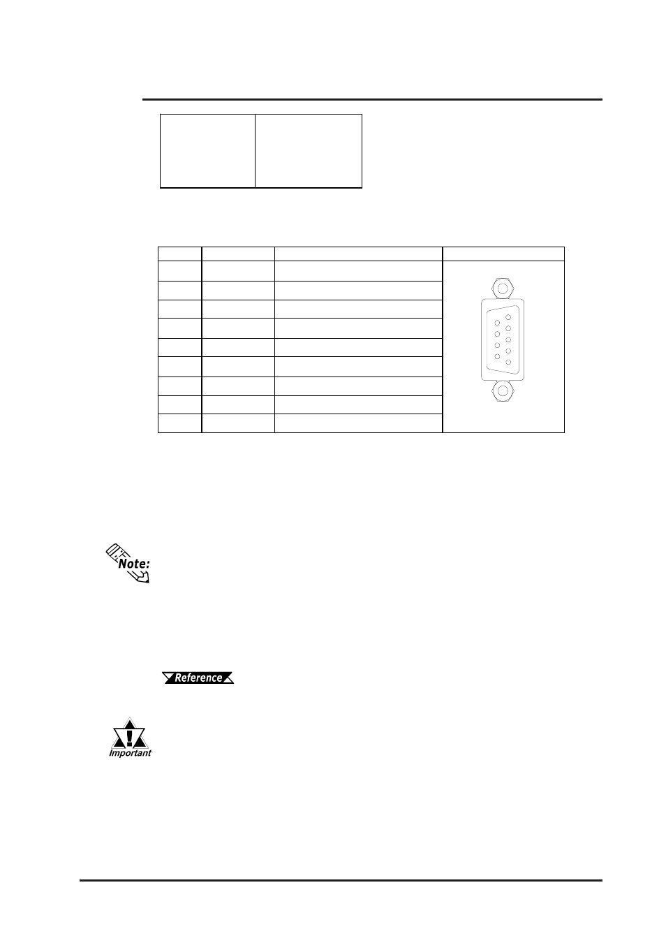
Pin Assignments and Signal Names
Connector:
Dsub 9 pin female
Connector set screw: Inch type (4-40)
RS-232C Cable:
FP61V-IS00-O <5m> manufactured by Digital Electronics
Corporation of Japan
*1 CD, DTR, and DSR are connected together inside the FP.
If a cable other than the specified RS-232C cable is used, FP unit opera-
tion cannot be guaranteed due to the possibility of noise interference.
6
9
1
5
Pin No. Signal Name
Condition
Pin Location
1
CD
Carrier Detect
*1
2
RD
Receive Data (FP->Host)
3
SD
Send Data (FP<-Host)
4
DTR
Data Terminal Ready
*1
5
GND
Ground
6
DSR
Data Set Ready
*1
7
RS
Request to Send (FP<-Host)
8
CS
Clear to Send (FP->Host)
9
NC
(Used internally)
RS-232C Interface
Baud rate: 9600 bps
Data length: 8 bits
Parity: none
Stop bit: 1