Proface FP3900 - 19 Flat Panel" User Manual
Page 80
FP-2500/FP-2600 Series User Manual
7-9
7.3 Backlight Replacement
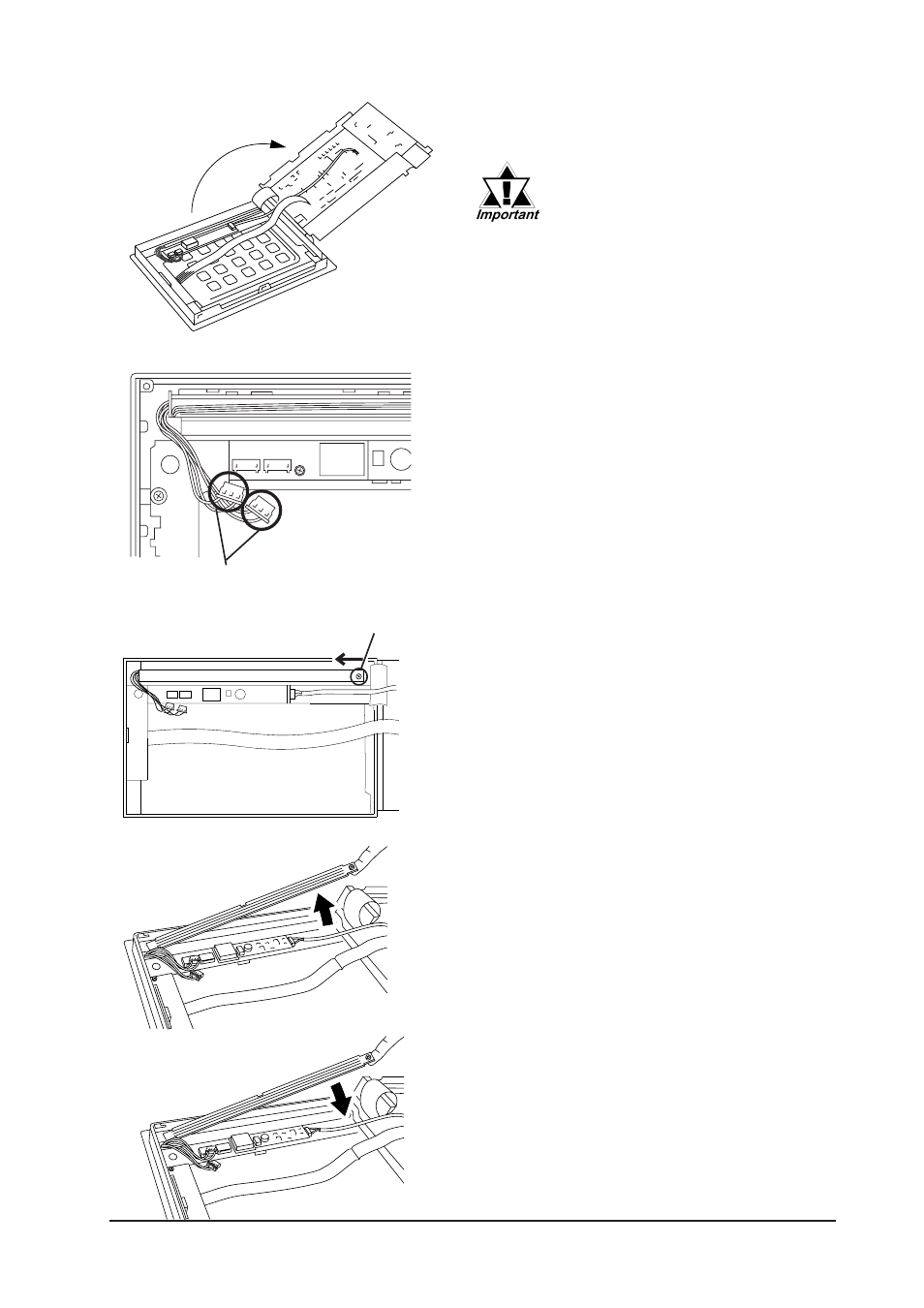
8) Connect the backlight's two (2) power
connectors. Next, close the circuit board
and secure the rear case in place using
the attachement screws removed in steps
1), 2) and 3).
5) Disconnect the backlight's two (2) power
connectors.
6) Loosen the backlight unit attachment
screw (the screw cannot be separated
from the backlight unit), slide the back-
light in the direction shown and remove it
from the FP.
7) Insert the new backlight in the FP. Insert
the unit by sliding it in the direction shown
in step 6), then, tighten the unit’s attach-
ment screw.
Upper Section
Lower Section
Attachment
Screw
4) The circuit board is connected on one
side, and hinges open.
When the FP unit's power has
just been turned OFF, the circuit
board chassis is still very hot!
Be sure to wear gloves to pre-
vent being burned.
Connector