Chapter 4 setting up and adjusting the fp unit, 1 operation mode setup, 1 dip switch preset settings and adjustments – Proface FP3900 - 19 Flat Panel" User Manual
Page 48: 1 operation mode setup -1, 1 dip switch preset settings and adjustments -1
FP-2500/FP-2600 Series User Manual
4-1
4.1.1 Dip Switch Preset Settings and Adjustments
4.1
Operation Mode Setup
Chapter 4
Setting up and Adjusting the FP unit
1. Operation Mode Setup
2. Screen Display Adjustment
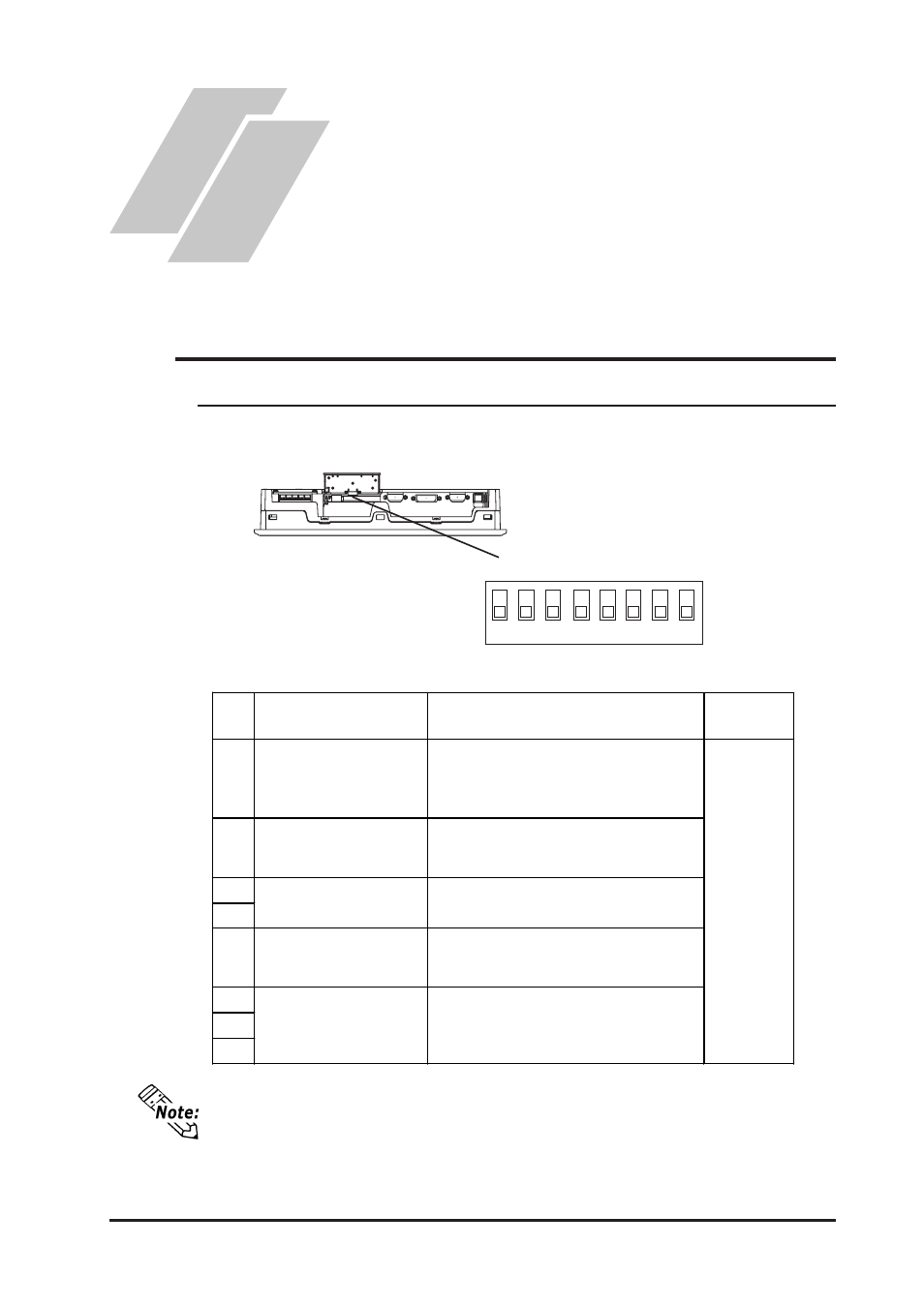
The FP unit's dip switches are located behind the Dip Switch Cover.
ON
SW1
8
6
5
4
3
2
7
1
SW
No.
Function
Description
Factory
Settings
1-1
Switch between USB and RS-
232C for touch panel data
transmission.
Used to set the touch panel data input (command
control) method to either USB or RS-232C.
ON : USB
OFF : RS-232C (Default setting)
1-2 Display/hide the OSD.
Used to display or hide the OSD.
ON : Hide
OFF : Display (Default setting)
1-3
1-4
1-5
Switch between analog RGB
and DVI-D input.
Used to change the image input method.
ON : DVI-D
OFF : analog RGB (Default setting)
1-6
1-7
1-8
All OFF
Reserved
Set this switch to OFF
Reserved
Be sure these switches are always set to OFF
Dip Switches
Dip switch settings are effective only when starting up the FP unit.
After changing any dip switch settings, be sure to restart your FP unit.