Proface AGP3500 - 10.4 DIO HMI" User Manual
Page 24
Monitoring the Ladder Programs of the External Device on a Display
PLC Ladder Monitor Operation Manual
2-9
7
Install the CF Card onto the GP.
Reference: For details on installing a CF Card, see “GP3000 Series Hardware Manual”.
8
Connect the display to communicate with the external device.
Reference: For details on the connection, see “GP-Pro EX Device Connection Manual”
9
Start up the Ladder Monitor.
There are four ways to start up the Ladder Monitor.
•
System menu
•
Switch parts
•
LS area
•
System variables:
#H_LadderMonitor (no cache)
#H_LadderMonitorCache (with cache)
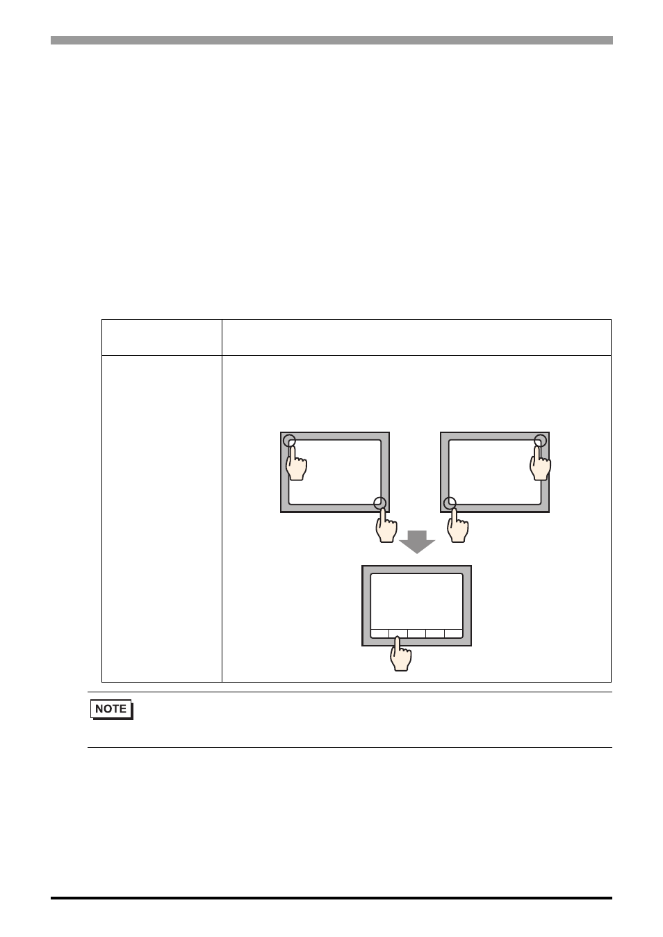
Ladder Monitor
Startup
Detail
Start up with the
System Menu
On the screen, touch the top left
→ on the bottom right (or the top
right
→ on the bottom left) in this order within 0.5 Seconds to
display the system menu. Touch the [Ladder Monitor] button to
display the main screen.
• To start up using switch parts or the LS area, see the following pages.
Start up procedure from switch parts” (page 2-5)
Start up procedure from the LS area” (page 2-7)
Ladder
Monitor
or
- AGP3400 - 7.5 DIO HMI" AGP3300 - 5.7 DIO HMI" AGP3600 - 12.1 FLEX Network HMIs" AGP3500 - 10.4 FLEX Network HMI" AGP3400 - 7.5 FLEX Network HMI" AGP3600 - 12.1 CANopen HMI" AGP3500 - 10.4 CANopen HMI" AGP3400 - 7.5 CANOpen HMI" AGP3300 - 5.7 CANopen HMI" AGP3300H - 5.7 Handheld HMIs" AGP3750 - 15 Multi-Media HMI" AGP3650 - 12.1 Multi-Media HMIs" AGP3550 - 10.4 Multi-Media HMIs" AGP3450 - 7.5 Multi-Media HMI" AGP3360 - 5.7 Multi-Media HMI" AST3300 - 5.7 Basic HMI" AST3200 - 3.8 Basic HMI" AGP3600 - 12.1 Standard HMIs" AGP3500 - 10.4 Standard HMIs" AGP3400 - 7.5 Standard HMI" AGP3300 - 5.7 Standard HMI" AGP3200 - 3.8 Standard HMI"