2 system configuration, System configuration -3, Communication cable connection – Proface AGP3500 - 10.4 DIO HMI" User Manual
Page 12
System Configuration
PLC Ladder Monitor Operation Manual
1-3
1.2
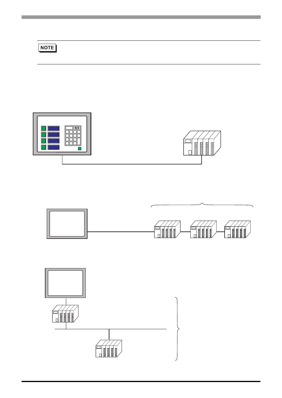
System Configuration
Communication Cable Connection
Display device units: Displays the connection status through the external device units.
•
The display and external device are connected 1:1 with a connection cable.
•
1-to-n connection (Only with link connection)
•
1-to-n connection (When accessing the link connection by surpassing the network.)
• For details regarding the connection of display devices and external devices,
refer to “CS/CJ Series HOST Link Drivers” or “CS/CJ Series Ethernet
Drivers” in the “GP-Pro EX Device Connection Manual.”
7
1
4
0
8
2
5
.
9
3
6
Production System Parameter Settings
CLR
DEL
Cancel
E
N
T
-
Display
CS1 series
Connection cable
Display
External
device
External
device
External
device
Up to 16 units
Display
External
device
External
device
Up to 16 units
- AGP3400 - 7.5 DIO HMI" AGP3300 - 5.7 DIO HMI" AGP3600 - 12.1 FLEX Network HMIs" AGP3500 - 10.4 FLEX Network HMI" AGP3400 - 7.5 FLEX Network HMI" AGP3600 - 12.1 CANopen HMI" AGP3500 - 10.4 CANopen HMI" AGP3400 - 7.5 CANOpen HMI" AGP3300 - 5.7 CANopen HMI" AGP3300H - 5.7 Handheld HMIs" AGP3750 - 15 Multi-Media HMI" AGP3650 - 12.1 Multi-Media HMIs" AGP3550 - 10.4 Multi-Media HMIs" AGP3450 - 7.5 Multi-Media HMI" AGP3360 - 5.7 Multi-Media HMI" AST3300 - 5.7 Basic HMI" AST3200 - 3.8 Basic HMI" AGP3600 - 12.1 Standard HMIs" AGP3500 - 10.4 Standard HMIs" AGP3400 - 7.5 Standard HMI" AGP3300 - 5.7 Standard HMI" AGP3200 - 3.8 Standard HMI"