2 peripheral interface connectors, Table 3-1: peripheral interface connectors – IEI Integration WAFER-CV-D25501_N26001 User Manual
Page 30
WAFER-CV-D25501/N26001 3.5" Motherboard
Page 15
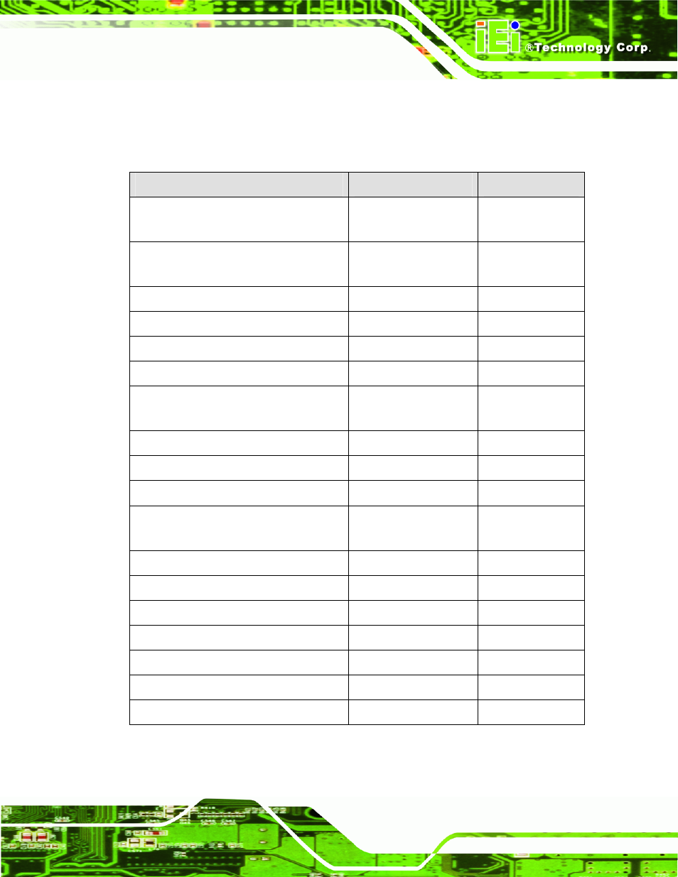
3.1.2 Peripheral Interface Connectors
The table below lists all the connectors on the board.
Connector
Type
Label
5 V SATA power connectors
2-pin wafer
SATA_PWR1,
SATA_PWR2
12 V power connector
4-pin Molex power
connector
CN3
Audio connector
10-pin box header
AUDIO1
Backlight inverter connectors
5-pin wafer
INV1, INV2
Battery connector
2-pin wafer
CN1
Digital Input/Output (DIO) connector
10-pin header
DIO1
Fan connectors
3-pin wafer
CPU_FAN1,
SYS_FAN2
Keyboard and mouse connector
6-pin wafer
KB_MS1
LVDS connectors
20-pin/30-pin crimp
LVDS1, LVDS2
LVDS2 backlight control connector
6-pin wafer
CN6
PCIe Mini card slots
52-pin PCIe Mini
M_PCIE1,
M_PCIE2
Power & HDD LED connector
6-pin header
CN2
Power button connector
2-pin wafer
PWR_BTN1
Reset button connector
2-pin wafer
RST_BTN1
RS-232 serial port connectors
10-pin header
COM2, COM3
RS-422/485 serial port connector
4-pin wafer
COM4
Serial ATA (SATA) drive connectors
7-pin SATA
SATA1, SATA2
USB 2.0 connectors
8-pin header
USB2, USB3
Table 3-1: Peripheral Interface Connectors