2 usb connectors, Figure 3-19: rj-45 ethernet connector, Table 3-19: lan pinouts – IEI Integration PICOe-B650 User Manual
Page 44: Table 3-20: rj-45 ethernet connector leds
PICOe-B650 Half-size PCIe CPU Card
Page 32
Pin Description Pin Description
1 MDIA3-
5 MDIA1+
2 MDIA3+
6 MDIA2+
3 MDIA2-
7 MDIA0-
4 MDIA1-
8 MDIA0+
Table 3-19: LAN Pinouts
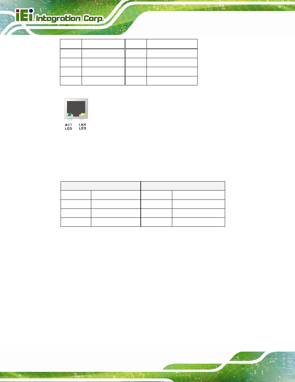
Figure 3-19: RJ-45 Ethernet Connector
The RJ-45 Ethernet connector has two status LEDs, one yellow (activity/link) and one
green/orange (speed). The yellow LED indicates activity/link on the port and the
green/orange LED indicates the connection speed. See
6
Table 3-20.
ACT/LINK LED
SPEED LED
STATUS
DESCRIPTION STATUS
DESCRIPTION
OFF
No Link
OFF
10 Mbps connection
YELLOW
Link
GREEN
100 Mbps connection
BLINKING
Data activity
ORANGE
1000 Mbps connection
Table 3-20: RJ-45 Ethernet Connector LEDs
3.3.2 USB Connectors
CN Label:
USB_C1, USB_C2
CN Type:
USB port
CN Location:
See
6
Figure 3-18
CN Pinouts:
See
6
Table 3-21
The PICOe-B650 has two external USB 2.0 ports. The ports connect to both USB 2.0 and
USB 1.1 devices.