3 external interface panel connectors, Table 3-1: peripheral interface connectors, Table 3-2: rear panel connectors – IEI Integration PICOe-B650 User Manual
Page 27
PICOe-B650 Half-size PCIe CPU Card
Page 15
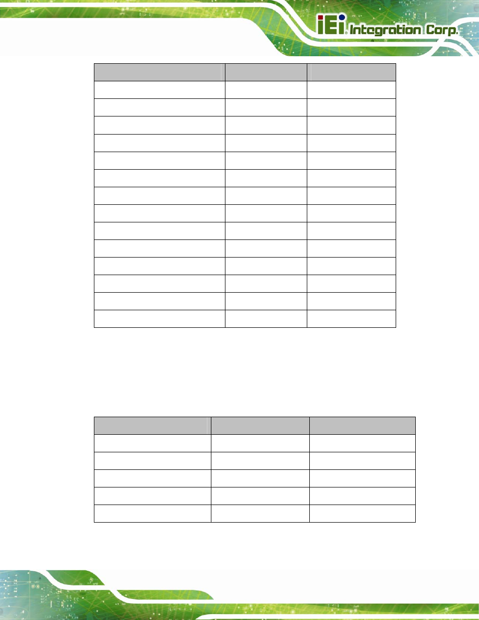
Connector
Type
Label
CPU fan connector
4-pin wafer
CPU_FAN1
CPU power connector
4-pin connector
CPU12V1
DDR3 SO-DIMM
204-pin SO-DIMM
DIMM1
Digital input/output (DIO) connector
10-pin header
DIO1
Front panel connector
10-pin header
F_PANEL1
I
2
C connector
4-pin wafer
I2C_1
Keyboard and mouse connector
6-pin wafer
KB_MS1
SATA 6Gb/s connector
7-pin SATA
SATA1
SATA 3Gb/s connector
7-pin SATA
SATA2
Serial port connectors (RS-232)
10-pin header
COM1, COM2
SMBus connector
4-pin wafer
SMBUS_1
SPI flash connector
6-pin wafer
JSPI1
TPM connector
20-pin header
TPM1
USB 2.0 connector
8-pin header
USB2
Table 3-1: Peripheral Interface Connectors
3.1.3 External Interface Panel Connectors
5
Table 3-2 lists the rear panel connectors on the PICOe-B650. Detailed descriptions of
these connectors can be found in Section
5
3.3 on page
5
31.
Connector
Type
Label
Ethernet connector
RJ-45
LAN1
Ethernet connector
RJ-45
LAN2
USB 2.0 port
USB port
USB_C1
USB 2.0 port
USB port
USB_C2
VGA port connector
15-pin female
CRT1
Table 3-2: Rear Panel Connectors