3 external peripheral interface connector panel, 1 lan connectors, Xternal – IEI Integration PICOe-B650 User Manual
Page 43: Eripheral, Nterface, Onnector, Anel, Table 3-18: usb port connector pinouts
PICOe-B650 Half-size PCIe CPU Card
Page 31
Pin Description
Pin Description
1 VCC
2 GND
3 DATA-
4 DATA+
5 DATA+ 6 DATA-
7 GND
8 VCC
Table 3-18: USB Port Connector Pinouts
3.3 External Peripheral Interface Connector Panel
6
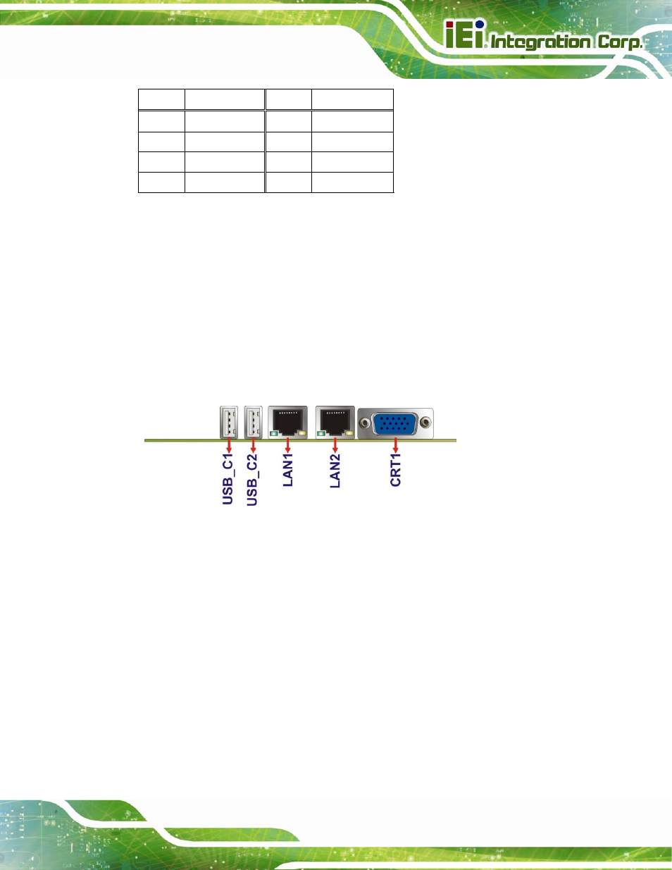
Figure 3-18 shows the PICOe-B650 external peripheral interface connector (EPIC) panel.
The PICOe-B650 EPIC panel consists of the following:
2 x RJ-45 LAN connectors
2 x USB connectors
1 x VGA connector
Figure 3-18: PICOe-B650 External Peripheral Interface Connector
3.3.1 LAN Connectors
CN Label:
LAN1 and LAN2
CN Type:
RJ-45
CN Location:
See
6
Figure 3-18
CN Pinouts:
See
6
Table 3-19
The PICOe-B650 is equipped with two built-in RJ-45 Ethernet controllers. The controllers
can connect to the LAN through two RJ-45 LAN connectors. There are two LEDs on the
connector indicating the status of LAN. The pin assignments are listed in the following
table: