A.O. Smith 12 40GPC T 100 User Manual
Page 40
40
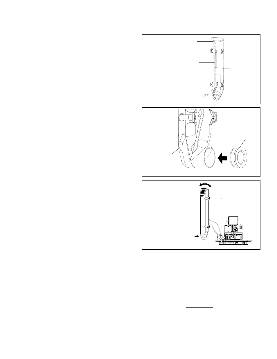
Installing the Air Intake Chamber Box:
11. Check the position the wiring harness wire in the
wiring channeling molded down the back center of
the air intake chamber box (Figure 78).
12. Connect the air pressure tubing to the fitting on
the bottom of the air intake chamber box and route
tubing in molded inlaid of the air intake chamber
box (Figure 78).
13. Reinstall the air intake chamber gasket (removed
in step 7) on the back lower portion of the air
intake chamber box (Figure 79).
14. Install the air intake chamber box to the
combustion chamber pipe. Using a small amount
of soapy water will help. Do not get any water
or soapy water on any electrical connections or
gas control components (see Figure 80), (NOTE:
UNDUE PRESSURE OR SUDDEN FORCE
SUCH AS HAMMERING OR BEATING ON
THE AIR CHAMBER BOX WITH ANY OBJECT
INCLUDING YOUR HANDS WILL DAMAGE THE
AIR INTAKE CHAMBER BOX AND RESULT IN
FAILURE OF THE HEATER’S OPERATION).
15. Install the air intake chamber box by rotating
the top of the air intake chamber box from left to
right (only a few inches in both directions) while
pressing on the bottom portion of the air intake
chamber box. When properly installed the air
intake chamber box will be in place against the
water heater’s side aligning with the screw holes
(Figure 80).
16. Secure the air intake chamber box to the water
heater’s side by reusing the 4 screws removed in
step 6 (Figure 80).
17. Reattach the air pressure tubing to the air
pressure switch by pushing the tubing onto the
connector until the end of the tubing pushes to the
shoulder of the connector.
18. Check the air hose tubing connection to the
pressure switch to ensure the tubing has not
loosened up or pulled off.
19. Turn on the electrical and the gas supplies to the
water heater. Plug in the electric connection from
the transformer to the electric outlet (Figure 75).
20. Restart the water heater by following the
directions on the “Lighting and Operating
Instructions” label located on the front of the water
heater.
21. Upon verifying proper operation of the water
heater, replace the manifold cover/outer door.
Figure 78.
RUBBER WIRE
PROTECTOR
WIRE HARNESS INSIDE
WIRE CHANNELING
AIR PRESSURE TUBING
CONNECTION
REAR SIDE OF
THE AIR INTAKE
CHAMBER BOX
Figure 79.
NEW AIR INTAKE
CHAMBER BOX
REINSTALL
CHAMBER GASKET
Figure 80.
ROTATE FROM
LEFT TO RIGHT
AND
PUSH INWARD