A.O. Smith 12 40GPC T 100 User Manual
Page 38
38
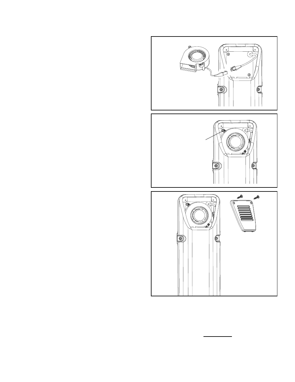
Installing the Fan in the Air Intake Chamber Box:
11. Plug the electrical connections of the new fan
into the wiring harness: Align the electrical
connections in such a position as to ensure the
locking portions of the connections are on the
same side. Gently push the electrical connectors
together until the snap lock on the wiring
harness engages the angular lock on the fan
connector. Do Not use undue force in pushing
these connectors together (Figure 71). (Note:
Connectors are designed in such a manner if the
connection is not properly aligned they will not
lock together).
12. Place the new fan inside the air intake chamber
box. It is imperative that the square portion of
the fan air outlet be placed inside the raised
square portion of the air intake chamber of the fan
compartment (Figure 72).
13. Ensuring the new fan is properly aligned in the air
intake chamber, secure the fan in place using the
2 screws removed in step 7 (Figure 72).
14. Route the wiring inside the fan box to the outer
edge of the fan in such a manner to ensure it will
not be pinched or damaged upon installation of
the air intake screen (Figure 72).
15. Install the air intake chamber screen, ensuring that
the prongs of the lower portion of the air intake
chamber screen are in place in the holding slots.
Using the 2 screws removed in step 4, secure the
air intake chamber screen (Figure 73).
16. Turn on the electrical and the gas supplies to the
water heater. Plug in the electric connection from
the transformer to the electric outlet (Figure 69).
17. Restart the water heater by following the
directions on the “Lighting and Operating
Instructions” label located on the front of the water
heater.
18. Upon verifying proper operation of the water
heater, replace the manifold cover/outer door.
Figure 71.
GENTLY PUSH THE ELECTRICAL
CONNECTORS TOGETHER UNTIL
IT IS SNAP LOCKED.
FAN
Figure 72.
INSTALL THE FAN USING THE
TWO SCREWS REMOVED
EARLIER.
FAN
Figure 73.
INSTALL THE AIR INTAKE
CHAMBER SCREEN.