A.O. Smith 12 40GPC T 100 User Manual
Page 27
27
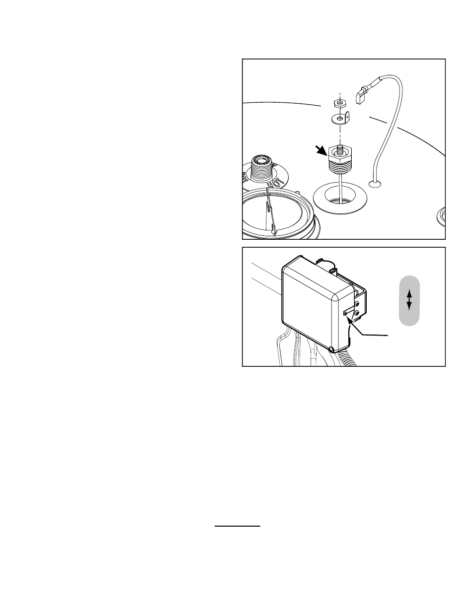
Installing the Powered Anode Rod:
8. Use Teflon
®
tape or an approved pipe sealant on
threads of the new powered anode rod.
9. Prior to installing, it will be necessary to use pliers
to bend up approximately 90° the electrical male
connector on the top of the powered anode rod.
The electrical connector should be bent upward
in order to allow the 1-1/16” deep well socket to
pass over the connector. Note: if using a short well
socket the male connector must first be removed
(Figure 34 is shown exploded for clarity).
10. Place the powered anode rod in the spud (top
of the tank) and turn clockwise until the threads
are hand tight. Using a ratchet and 1-1/16” socket
tighten down water tight (Torque should be
between 65 to 120 foot pounds).
11. Open a nearby hot water faucet to purge air from
the water line. Fill water heater tank completely
(Note: to assure the water heater tank is full, keep
the hot water faucet open for 3 minutes after a
constant flow of water is obtained).
12. After turning off the hot water faucet, check for
water leaks around powered anode rod and
immediately correct any if found.
13. Upon determining there’s no water leak at the
newly installed powered anode rod, reconnect the
electrical plug connector to the top of the anode
male terminal.
14. Plug the electric transformer in the wall outlet and
turn the gas supply back on to the gas control
valve/thermostat.
15. Turn the gas control switch to the “ON” position
(located on the side of the gas control valve/
thermostat see Figure 35).
16. To restart the water heater, follow the directions
on the “Lighting and Operating Instructions” label
located on the front of the water heater near the
gas control valve/thermostat.
17. Upon verifying proper operation of the water
heater, replace the manifold cover outer door.
Teflon
®
is a registered trademark of E.I. Du Pont De Numours and Company.
Powered
Anode
Rod
Figure 34.
ON/OFF
SWITCH
ON
OFF
Figure 35.