Know the water heater’s component parts – A.O. Smith 12 40GPC T 100 User Manual
Page 12
12
KNOW THE WATER HEATER’S COMPONENT PARTS
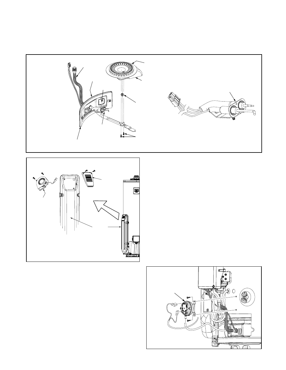
Burner/Manifold Door Assembly
The burner/manifold door assembly consists of several components such as: main burner, burner orifice,
manifold tube and flame sense / hot surface igniter. See figure below for the complete list of components
(Figure 13).
*DO NOT operate the water heater without the burner orifices installed.
Burner Screws
Main Burner
Manifold
Tube
Door Gasket
Burner Orifice*
Manifold
Door
View
Port
Flame Sense/
Hot Surface
Igniter Assembly
Flame Sense / Hot Surface
Igniter Assembly
Scoop side to be placed
on the same side as
View Port.
Figure 13.
Air Intake Chamber Fan
The small fan at the top of the air intake chamber
on the side of the water heater is used to draw in
necessary combustion air for the efficient operation
of the main burner. The fan pressurizes the sealed
combustion chamber which in turn allows the flue
baffle inside the center flue tube to slow down the
hot exhaust gases so heat can be extracted into the
water before exiting into the vent system. The air
intake chamber fan runs for about 5 seconds to pre-
purge the combustion chamber before the beginning
of an ignition sequence when there is a call for
heat. The fan will continue to operate while the main
burner is in operation and for about 5 seconds after
the temperature set point has been achieved. The
air intake chamber screen covering the fan should
be inspected and cleaned periodically to assure it is
not limiting air flow into the chamber (Figure 14).
Pressure Switch
A pressure switch in the control string of this water
heater is used to verify there is an adequate flow of
combustion air into the combustion chamber before
and during main burner operation. It is electrically
connected to the gas control valve/thermostat and
controls the opening and closing of the gas valve.
If there is an insufficient air supply being delivered
to the combustion chamber the pressure switch will
not allow the water heater to operate (Figure 15).
Air intake
Chamber
Air intake
Chamber
Screen
Air intake
Chamber
Fan
Figure 14.
Pressure
Switch
Figure 15