A.O. Smith 12 40GPC T 100 User Manual
Page 30
30
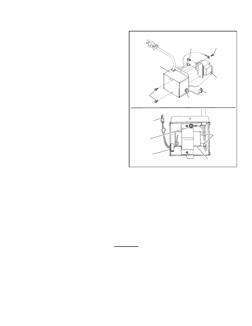
Installing the New Transformer:
10. Insert the wiring connector that goes to the gas
control valve/thermostat through the wire protector
on the side of the transformer box (Figure 44).
11. Attach the two (2) flag terminal connectors to
the transformer by aligning and pressing down
(Figure 44).
12. Position the new transformer inside the
transformer box where the wiring connections are
nearest their exit points (Figure 44).
13. Align the holes of the transformer mounting
bracket to the hole of the transformer box and
attach using the 2 hex head screws (Note:
take care not to pinch any wiring between the
transformer and the transformer box) (see
Figure 44).
14. Insert the ground wire connector through the
ground screw and tighten in place with a phillips
head screwdriver (Figure 44).
15. Using the screw removed in step 6, reattach the
transformer box to the water heater’s side.
16. Reattach the power supply transformer connector
to the bottom of the gas control valve/thermostat
by aligning and pushing upward (Figure 42).
17. Plug the electric transformer in the wall outlet and
turn the gas supply back on to the gas control
valve/thermostat (Figure 41).
18. Turn the gas control switch to the “ON” position
(Figure 41).
19. To restart the water heater, follow the directions
on the “Lighting and Operating Instructions” label
located on the front of the water heater near the
gas control valve/thermostat.
20. Upon verifying proper operation of the water
heater, replace the manifold cover outer door.
Figure 44.
TRANSFORMER
GROUND
SCREW
TRANSFORMER
BOX
ELECTRICAL
FLAG TERMINALS
HEX HEAD
SCREWS
GROUND
SCREW
ELECTRICAL
FLAG
TERMINALS
TRANSFORMER
POWER SUPPLY
TRANSFORMER
CONNECTOR
POWER SUPPLY
TRANSFORMER
CONNECTOR
WIRE
PROTECTOR
WIRE
PROTECTOR