Wiring harness removal / replacement – A.O. Smith 12 40GPC T 100 User Manual
Page 34
34
WIRING HARNESS REMOVAL / REPLACEMENT
Important: Use only factory authorized replacement
parts. If you lack the necessary skills to properly
perform the installation, you should not proceed, but
get help from a qualified service technician.
Tools required: Phillips Head Screwdriver.
Removing the Air Intake Chamber Box:
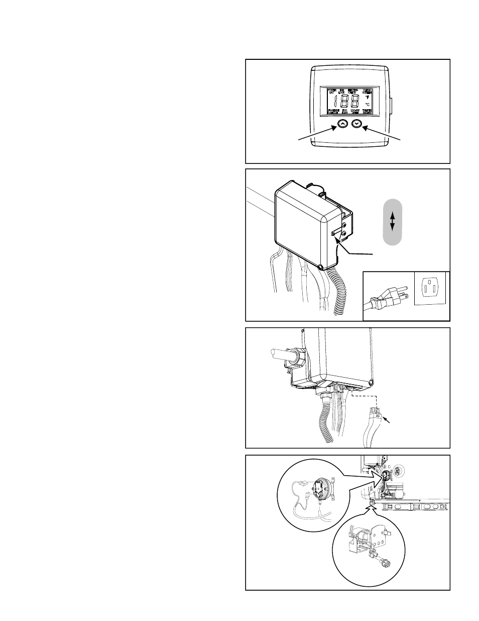
1. Set the gas control valve/thermostat to its lowest
setting by pressing the “COOLER” and “HOTTER”
buttons together at the same time holding for 1
second. Then press the “COOLER” button to the
lowest setting (Figure 57).
2. Turn gas control switch to the “OFF” position
(located right side of the gas control valve/
thermostat) and turn off the gas supply to the unit
(Figure 58).
3. Disconnect the electric connection by unplugging
the transformer from the wall outlet (Figure 58).
4. Remove the manifold cover/ outer door from the
unit by depressing on the lower portion and pulling
outward.
5. Unplug the 3-wire pressure switch/fan/sensor
electrical connection of the wiring harness from
the gas control valve/thermostat by depressing the
lower portion of the snap clip to open and pulling
down the connector (Figure 59).
6. Unplug the electric flag terminals and air pressure
tubing from the pressure switch (Figure 60).
7. Remove the FV sensor by depressing the snap
lock to open the FV sensor cover, slide the FV
sensor out of the cover and unplug the electrical
flag terminals connections (Note: place the FV
sensor in a safe place as it will be reinstalled later)
(Figure 60).
8. Using a phillips head screwdriver remove the 2
screws of the air intake chamber screen (Note:
save screws for reinstallation later) (Figure 62).
9. Remove the air intake chamber screen by lifting
upward and outward (Figure 62).
10. Please take note of the wire position routing
around the fan inside the air intake chamber as
this wire positioning will need to be duplicated
upon installation of the new wiring harness
(Figure 62).
11. Using a phillips head screwdriver, remove the 4
screws securing the air intake chamber box to the
water heater’s side (also keeping these screws in
a safe place for reinstallation later) (Figure 61).
12. Rotate the top of the air intake chamber box from
left to right (only a few inches in both directions)
while pulling outward at the bottom removing
the air intake chamber box from the combustion
chamber pipe saving the air intake chamber
gasket for reinstallation (Figure 61).
GAS CONTROL
VALVE/THERMOSTAT
PRESSURE
SWITCH/FAN,
FV SENSOR
CONNECTOR
Figure 59.
Figure 60.
FV SENSOR
PRESSURE
SWITCH
PRESSURE TUBING & WIRING
HARNESS FLAG TERMINALS
g
COOLER
HOTTER
Electronic Control Display
Figure 57.
ON/OFF
SWITCH
ON
OFF
Figure 58.
UNPLUGGED