Transformer removal / replacement, On/off switch on off – A.O. Smith 12 40GPC T 100 User Manual
Page 29
29
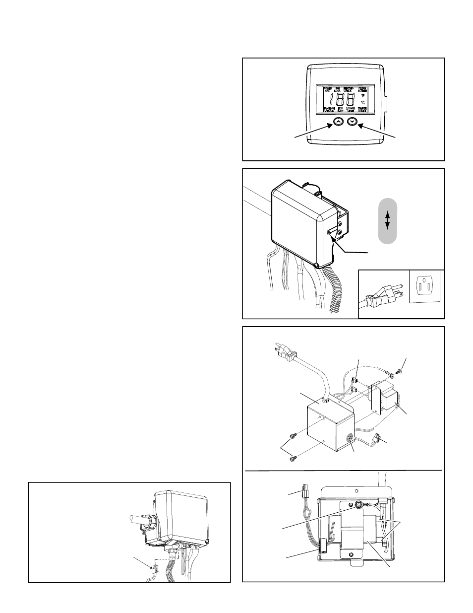
TRANSFORMER REMOVAL / REPLACEMENT
g
COOLER
HOTTER
Electronic Control Display
Figure 40.
ON/OFF
SWITCH
ON
OFF
Figure 41.
UNPLUGGED
Important: Use only factory authorized replacement parts.
If you lack the necessary skills to properly perform the
installation, you should not proceed, but get help from a
qualified service technician.
Tools required: Ratchet with
5/16
” Socket or
5/16
” Nut
Driver, Phillips Head Screwdriver.
Removing the Transformer:
1. Set the gas control valve/thermostat to its lowest
setting by pressing the “COOLER” and “HOTTER”
buttons together at the same time holding for 1
second. Then press the “COOLER” button to the
lowest setting (Figure 40).
2. Turn gas control switch to the “OFF” position
(located right side of the gas control valve/
thermostat) and turn off the gas supply to the unit
(Figure 41).
3. Disconnect the electric connection by unplugging
the transformer from the wall outlet (Figure 41).
4. Remove the manifold cover outer door from the
heater by depressing on the lower portion and
pulling outward.
5. Unplug the power supply transformer connector
from the bottom of the gas control valve by
pressing the snap connector and pulling
downward (Figure 42). (NOTE: The transformer is
located inside the transformer box adjacent to the
gas control/thermostat valve).
6. Using a phillips head screwdriver, remove the
transformer box from the side of the water heater
by removing the single screw securing it to the
water heater’s side (Note: keep screw in a safe
place for reinstalling later).
7. Using a phillips head screwdriver remove the
ground screw from the inside of the transformer
box (Note: save the screw for reinstallation later)
(see Figure 43).
8. Take note of the position of the transformer, use
a 5/16” nut driver or a ratchet with a 5/16” socket
to remove the 2 hex head screws on the front of
the transformer box (Note: save the screws for
reinstallation later) (see Figure 43).
9. Unplug the two flag terminal electrical connections
on the transformer and pull the wiring and
connector through the wire protector (Figure 43).
Figure 43.
TRANSFORMER
GROUND
SCREW
TRANSFORMER
BOX
ELECTRICAL
FLAG TERMINALS
HEX HEAD
SCREWS
GROUND
SCREW
ELECTRICAL
FLAG
TERMINALS
TRANSFORMER
POWER SUPPLY
TRANSFORMER
CONNECTOR
POWER SUPPLY
TRANSFORMER
CONNECTOR
WIRE
PROTECTOR
WIRE
PROTECTOR
Gas Valve
Wire Connector
Gas Control
Valve/Thermostat
Figure 42.
POWER SUPPLY
TRANSFORMER
CONNECTOR
GAS CONTROL
VALVE/THERMOSTAT