Air intake chamber fan removal / replacement – A.O. Smith 12 40GPC T 100 User Manual
Page 37
37
AIR INTAKE CHAMBER FAN REMOVAL / REPLACEMENT
Important: Use only factory authorized replacement
parts. If you lack the necessary skills to properly
perform the installation, you should not proceed, but
get help from a qualified service technician.
Tools required: Phillips Head Screwdriver.
Removing the Fan from the Air Intake Chamber:
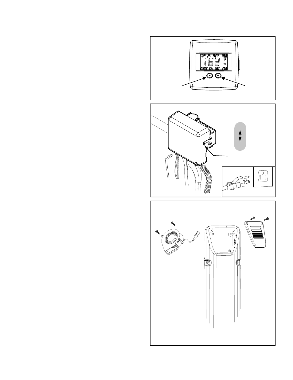
1. Set the gas control valve/thermostat to its lowest
setting by pressing the “COOLER” and “HOTTER”
buttons together at the same time holding for 1
second. Then press the “COOLER” button to the
lowest setting (Figure 68).
2. Turn gas control switch to the “OFF” position
(located right side of the gas control valve/
thermostat) and turn off the gas supply to the unit
(Figure 69).
3. Disconnect the electric connection by unplugging
the transformer from the wall outlet (Figure 69).
4. Using a phillips head screwdriver, remove the two
(2) screws at the air intake chamber screen (Note:
save screws for reinstallation later) (Figure 70).
5. Remove the air intake chamber screen by lifting
upward (Figure 70).
6. Take note of the wire position routing around
the fan inside of the air intake chamber as this
wire positioning will need to be duplicated upon
installation of the new fan inside the intake
chamber box.
7. Remove the 2 screws securing the old fan
inside the chamber (Note: save these screws for
reinstallation later) (Figure 70).
8. Lift the old fan up and outward to remove from the
air intake chamber (Figure 70).
9. Locate the male to female electrical connection
with close pin lock on wiring harness (the white
connection approximately 12” from fan).
10. To separate the electrical connection of the fan
and wiring harness: press down on the back
portion of the close pin lock of the electrical
connection while pulling the connection in the
opposite directions.
Figure 70.
SCREEN
FAN
AIR INTAKE
CHAMBER BOX
g
COOLER
HOTTER
Electronic Control Display
Figure 68.
ON/OFF
SWITCH
ON
OFF
Figure 69.
UNPLUGGED