Installation instructions – WEATHER GUARD 246-3-02 through 396-5-02 User Manual
Page 3
3
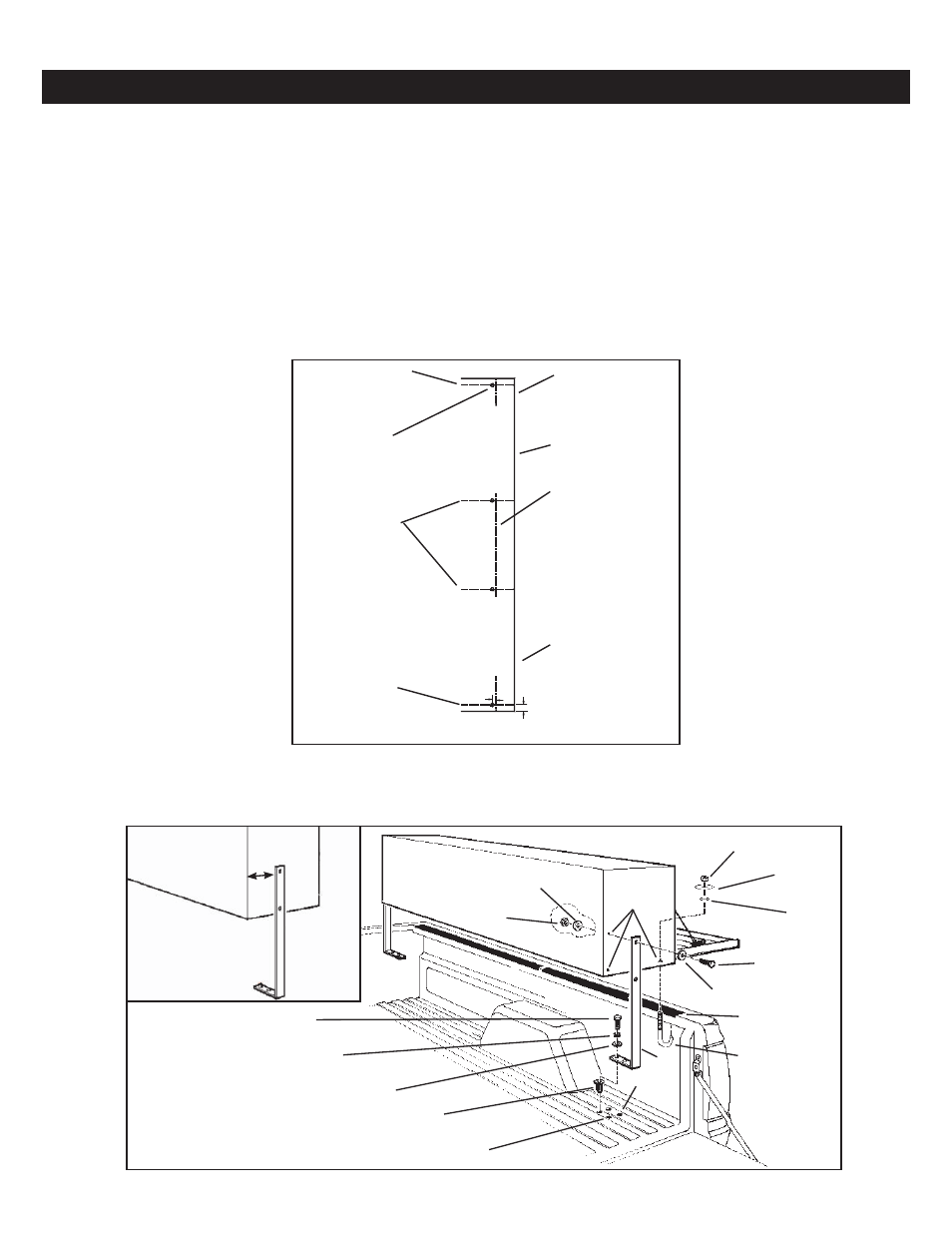
STEP 3. Place the Mounting Pads in position on top of the truck bed (as shown in Figure 2.). Tape the Mounting Pads to the truck
bed in a few places to keep them from moving or falling off when installing the box.
NOTE: If installing the box on top of a stake bed, disregard these instructions. Mount the box with the bottom fully
supported or structural damage will occur to the box.
NOTE: When installing in a pickup bed the box must be installed per these instructions using the mounting legs supplied.
This box must never be bolted to a ladder rack or structural damage will occur to the box.
NOTE: To prevent rust from occurring, touch-up any drilled holes.
STEP 1. Park the vehicle as level as possible.
STEP 2. Turn the box over, and at each end of the box, mark a 6" long line 7/8" in from and parallel to the end. Start the line at
the front of the bottom (see Figure 1). For Models 272-3-02/290-3-02/291-3-02/296-3-02/297-3-02/ 372-X-02/390-X-02/391-X-
02/396-X-02, mark a 6" long line centered side to side on the box, 12" apart (see Figure 1.).
INSTALLATION INSTRUCTIONS
Mark this line
even with bed lip-
only for Models
272-3-02/290-3-02
291-3-02/296-3-02
297-3-02/372-X-02
390-X-02/391-X-02
396-X-02
Front
of Box
6" long line-
7/8" in from
end of box
Line marked
even with
bed lip
Figure 1. Box Marking
6" long lines-
centered
side to side
12" apart-
only for Models
272-3-02/290-3-02
291-3-02/296-3-02
297-3-02/372-X-02
390-X-02/391-X-02/396-X-02
6" long line-
7/8" in from
end of box
Line marked
even with
bed lip
3/8" Holes -
typical unless
stake beds interfere -
see instruction text
1/2"
7/8"
5/16-18 x 1-1/4"
Hex Head Bolt
5/16 Lock
Washer
5/16 Flat
Washer
Blind
Fastener
1/2" Hole
3/8" Holes
5/16-18 Nylon
Lock Nut
5/16 Flat
Washer
5/16-18 Nylon
Lock Nut
Fender
Washer
Plastic
Retaining
Washer
5/16-18 x 1"
Hex Head Bolt
5/16 Flat
Washer
Mounting
Pad
"J" Bolt
Figure 2. Main Assembly View
Leg
See
NOTE 1
3"
Max.
- Model 396-5-02 Hi-Side Box, Aluminum, 11.8 cu ft Model 396-0-02 Hi-Side Box, Aluminum, 11.8 cu ft Model 391-5-02 Super-Side Box, Aluminum, 15.2 cu ft Model 390-5-02 Hi-Side Box, Aluminum, Driver Side, 11.1 cu ft Model 390-0-02 Hi-Side Box, Aluminum, Driver Side, 11.1 cu ft Model 372-5-02 Hi-Side Box, Aluminum, Driver Side, 8.9 cu ft Model 372-0-02 Hi-Side Box, Aluminum, Driver Side, 8.9 cu ft Model 365-5-02 Super Hi-Side Box, Aluminum, 10.8 cu ft Model 365-0-02 Super-Side Box, Aluminum, 10.8 cu ft Model 364-5-02 Hi-Side Box, Aluminum, 7.9 cu ft Model 364-0-02 Hi-Side Box, Aluminum, 7.9 cu ft