Warner Electric MCS-208 User Manual
Page 7
Warner Electric • 800-825-9050
P-276 • 819-9045
7
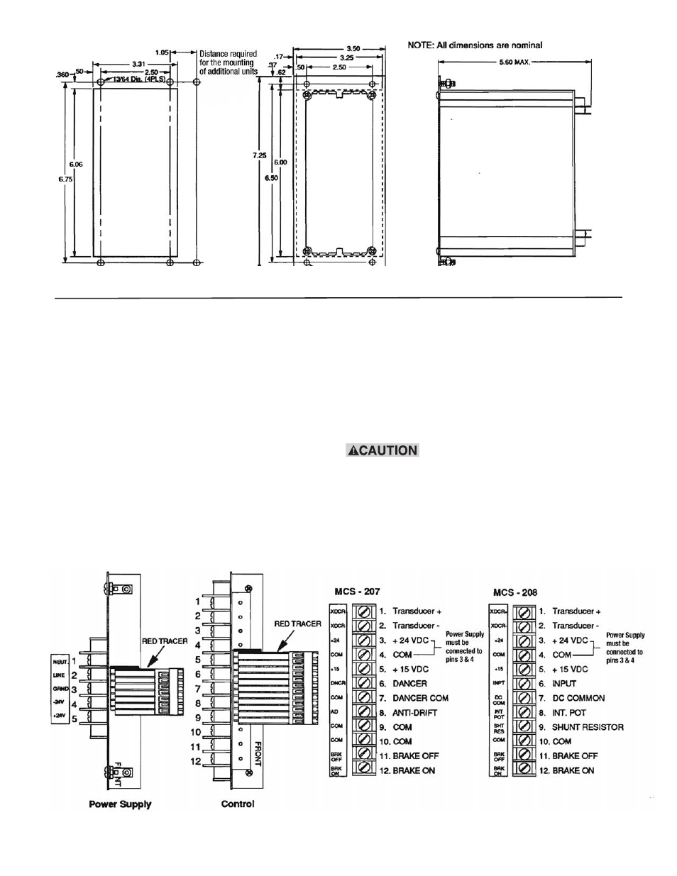
Figure 5. Panel mount cut-out dimensions
Figure 6. Panel mount housing dimensions
B. Panel Mounting
NoTe: Panel mount housings cannot be joined
together.
1. If the PC Board assemblies have been installed, it
will be necessary to remove them. Simply loosen
the captive screws which are located on the front
panels and slide the assemblies out.
2. Using the dimensions shown in Figure 5, cut an
opening 3-5/16 x 6-1/16” into the mounting panel
for each housing assembly.
3. Using the dimensions shown in Figure 5, drill four
(4) 13/64” mounting holes for each housing to
provide clearance for the #10 mounting studs.
4. Slide the housing assemblies into the mounting
panel cutouts. Securely fasten the housings to
the mounting panel with the four nuts on each
housing.
5. Apply the terminal strip label to the housing
panel near the terminal block as shown in
Figure7.
Be sure to apply the label in the
proper position with the transducer (+) terminal at
the top.
The controls are now ready to be wired. Proceed to the
wiring section of this manual for the appropriate wiring
instructions.
Figure 7. Terminal strip label orientation for Panel Mount