Warner Electric MCS-208 User Manual
Page 2
2
Warner Electric • 800-825-9050
P-276 • 819-9045
Contents
Introduction . . . . . . . . . . . . . . . . . . . . . . . . . . . . . . . . 2
System Components . . . . . . . . . . . . . . . . . . . . . . . . . 3
Specifications. . . . . . . . . . . . . . . . . . . . . . . . . . . . . . . 3
Installation
Control Housings . . . . . . . . . . . . . . . . . . . . . . . . . 5
Sensor. . . . . . . . . . . . . . . . . . . . . . . . . . . . . . . . . . 8
Air Disc Tension Brake . . . . . . . . . . . . . . . . . . . . . 9
T-6000 Transducer . . . . . . . . . . . . . . . . . . . . . . . 10
System Wiring
MCS-166/MCS-207 . . . . . . . . . . . . . . . . . . . . . . . 9
MCS-166/MCS-208 . . . . . . . . . . . . . . . . . . . . . . 10
System Start-Up and Adjustments
MCS-166/MCS-207/Transducer . . . . . . . . . . . . . 12
MCS-166/MCS-208/Transducer . . . . . . . . . . . . . 18
System Troubleshooting
Dancer Tension Control System . . . . . . . . . . . . . 23
Remote/Analog Control Sytem . . . . . . . . . . . . . . 25
Replacement Parts Listing . . . . . . . . . . . . . . . . . . . . 25
Listing of Figures and Illustrations . . . . . . . . . . . . . . 25
Failure to follow these
instructions may result in product damage,
equipment damage, and serious or fatal injury
to personnel.
NoTeS: Installation must be made in accordance
with the instructions found in this manual. Failure to do
so may damage the controls and void their warranty.
Contact with the electrical voltages
present in the controls covered in this manual can
cause injury or death. To avoid these consequences,
make sure all power is off during installation.
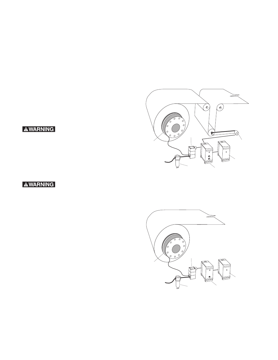
Introduction
Warner Electric offers two pneumatic tension control
systems. The Dancer Tension Control System consists
of: an Air Disc pneumatic tension brake, an
electro-pneumatic transducer, an oil removal filter, an
MCS-166 power supply, an MCS-207 control module,
and a pivot point sensor. Figure 1 shows the system
diagram for these components.
The Remote/Analog Control System consists of: an Air
Disc pneumatic tension brake, an electro-pneumatic
transducer, an oil removal filter, an MCS-166 power
supply, an MCS-208 Remote Analog control module,
and an input control device. (Figure 2 shows these
components in a local torque adjust operating mode.)
Consult Warner Electric if assistance is required in
selecting an input control device.
This manual has been designed to cover the full range
of installation, startup, operation, and maintenance
procedures for your tension control system. System
selection information can be found in Warner Electric’s
Tension Control Systems Catalog, P-771.
Air Disc
Tenison Brake
with Guard
Pivot Point
Sensor
Filter
Transducer
MCS-166
Power Supply
MCS-207
Control
Air Disc
Tenison Brake
with Guard
MCS-166
Power Supply
MCS-208
Control
Filter
Transducer