Warner Electric Electric Wheel Brake 12-1_4 x 3-1_2 Replacement User Manual
Page 8
8
Warner Electric • 800-825-9050
819-0209
can stick in their expanded position. To
correct this, merely push the shoe back
into position. Once the shoe drum has
been installed, the shoe will be restricted
from expanding far enough to stick.
15. Reassemble the drum and wheel. Make
sure wheel bearings and wheel nuts are
adjusted to axle manufacturer’s specifica-
tions.
Case III: Replacing Dual Magnets on Old
Style Magnet Arm with New Single Magnet
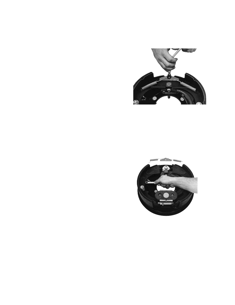
1. Remove the two shoe return springs (4-1),
using a brake spring tool. (See Figure 17).
2. Remove the anchor pin plate (4-2) and
spread the shoe (2-1) apart, exposing the
brake terminal assembly (6).
On right-hand brakes allow 2-3/8-inches of
wire between the magnet and first clip.
(See Figure 15).
On left-hand brakes allow 3-1/8-inches of
wire between the magnet and first clip.
(See Figure 16).
Allowing this much wire prevents strain on
the wire when the magnet is pulled out the
maximum distance.
11. Assemble the magnet lead wire terminals
onto the terminal posts (6-3) in the follow-
ing sequence:
a. Place one internal lockwasher over each
post.
b. Place one wire terminal over each post.
c. Place one internal nut over each post
and tighten them to 30-40 in.-lb. torque.
12. Close the shoe (2-1) that was spread to
expose the terminal and install the anchor
pin plate (4-2).
13. Install the shoe return springs (4-1), using a
brake spring tool.
14. Move the magnet lever arm along its track
to insure that the shoes expand and con-
tract properly and are in correct adjust-
ment. When making this test, the shoes
Figure 17 - Removing Shoe Return Springs
Figure 18 - Removing Internal Nuts