Warner Electric Electric Wheel Brake 12-1_4 x 3-1_2 Replacement User Manual
Page 14
14
Warner Electric • 800-825-9050
819-0209
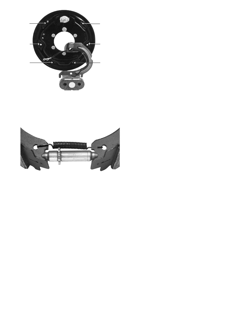
6. Assemble the two shoes (2-1), new adjuster
spring (3-5) and new adjuster (3-1, 3-2, and
3-3). Make sure the adjuster is fitted into the
notches in the shoe web. (See Figure 33).
7.
Reinstall the two shoes (2-1), the adjuster
(3-1, 3-2, and 3-3) and the adjuster spring
(3-5) as a complete assembly. The adjuster
nut (3-3) must be positioned over the brake
adjustment access hole in the backing
plate.
8.
Replace the rubber adjuster plug (3-4) from
the backside of the brake.
9.
To facilitate the installation of the shoe hold
down assemblies, rotate either shoe (2-1)
away from the anchor pin so that the shoe
slides off the shoe pad and onto the curl of
the backing plate. This procedure will mini-
mize the hold down spring compression
required.
10. As noted in Step 3, there are two shoe hold
down assembly configurations. Follow the
instructions for Style A or Style B to install
the shoe hold down assemblies.
Style A (old style): Insert the pin (with the
rubber washer on its head) through the rear
of the backing plate and through the hole in
the shoe web.
Place a dished washer, the spring, and
another dished washer over the pin end.
Compress the spring assembly below the
swaged end of the pin. Rotate the top
washer 90° to lock the assembly into place.
Style B (new style): Insert a hold down pin
(2-3) through the hole in the rear of the
backing plate and through the hole in the
shoe web (2-1). Hold the pin in place.
Place a spring cup (2-4), convex upward,
over the pin. Next install the spring (2-2), a
spring cup (2-4) convex downward, and
then a spherical washer (2-5) over the pro-
truding pin (2-3). The spherical washer
nests in the spring cup.
Slide a new “X” washer retainer (2-6)
between the head of the pin (2-3) and the
spherical washer (2-5) while compressing
the assembly. Using pliers, close the “X”
retainer to lock on the pin.
11. Lift the shoe (2-1) onto the shoe pads on
the backing plate with a heavy screw driver.
Rotate it into place against the anchor pin.
12. Repeat steps 9 through 11 for the second
shoe hold down assembly.
13. Install anchor pin plate (4-2).
14. Install shoe return springs (4-1) using a
brake spring tool.
15. Check that shoes expand and contract
properly and are in correct adjustment.
16. Reassemble drums and wheels. Make sure
wheel bearings and wheel nuts are adjust-
ed to axle manufacturer’s specifications.
17. Brake Adjustment
Remove the rubber adjuster plug (3-4), and
insert an adjusting tool. (See Figure 34).
With the wheel off the ground, expand the
Figure 32 - Lubricating Shoe Pads