Warner Electric Electric Wheel Brake 12-1_4 x 3-1_2 Replacement User Manual
Page 24
24
Warner Electric • 800-825-9050
819-0209
6.
Place a spring cup (2-4) convex upward,
over the pin. Next install the spring (2-2), a
spring cup (2-4) (convex downward), and
then a spherical washer (2-5) (it nests in the
spring cup) over the protruding pin (2-3).
7.
Slide a new “X” washer retainer (2-6)
between the head of the pin (2-3) and the
spherical washer (2-5) while compressing
the assembly. Using pliers, close the “X”
washer retainer to lock on the pin.
8.
Lift the shoe (2-1) onto the shoe pads on
the backing plate with a heavy screwdriver.
Rotate it into place against the anchor pin.
9.
Repeat steps 4 through 8 for the second
shoe hold down assembly.
10. Install the anchor pin plate (4-2).
11. Install the shoe return springs (4-1) using a
brake spring tool.
12. Move the magnet lever arm along its track
to ensure that the shoes expand and con-
tract properly and are in the correct adjust-
ment. When making this test, the shoes
can stick in their expanded position. To
correct this, merely push the shoe back
into position. Once the shoe drum has
been installed, the shoe will be restricted
from expanding far enough to stick.
13. Reassemble the drums and wheels. Make
sure the wheel bearings and wheel nuts are
adjusted to the axle manufacturer’s specifi-
cations.
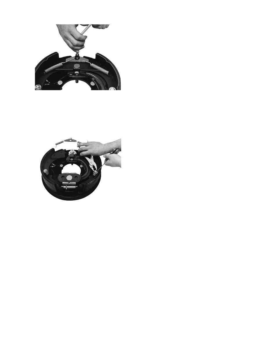
Depress the spring assembly, and using pli-
ers, squeeze the ears of the “X” washer
retainer (2-6) together to open it. Relax the
spring assembly and remove it.
(See Figure 55).
Discard the old “X” washer retainer (2-6).
Repeat this procedure for the second hold
down assembly.
4.
To facilitate the installation of the new style
shoe hold down assemblies, rotate either
shoe (2-1) away from the anchor pin so that
the shoe slides off the shoe pad and onto
the curl of the backing plate. This proce-
dure will minimize the hold down spring
compression required.
5.
Insert a hold down pin (2-3) through the
hole in the rear of the backing plate and the
hole in the shoe (2-1) web. Hold the pin in
place.
Figure 54 - Removing Shoe Return Spring
Figure 55 - Removing Shoe Hold
Down Assemblies