Warner Electric Electric Wheel Brake 12-1_4 x 3-1_2 Replacement User Manual
Page 13
13
Warner Electric • 800-825-9050
819-0209
Replacing the Adjuster/Adjuster Spring
Kit No. 1301-100-006
See page 3 for kit description.
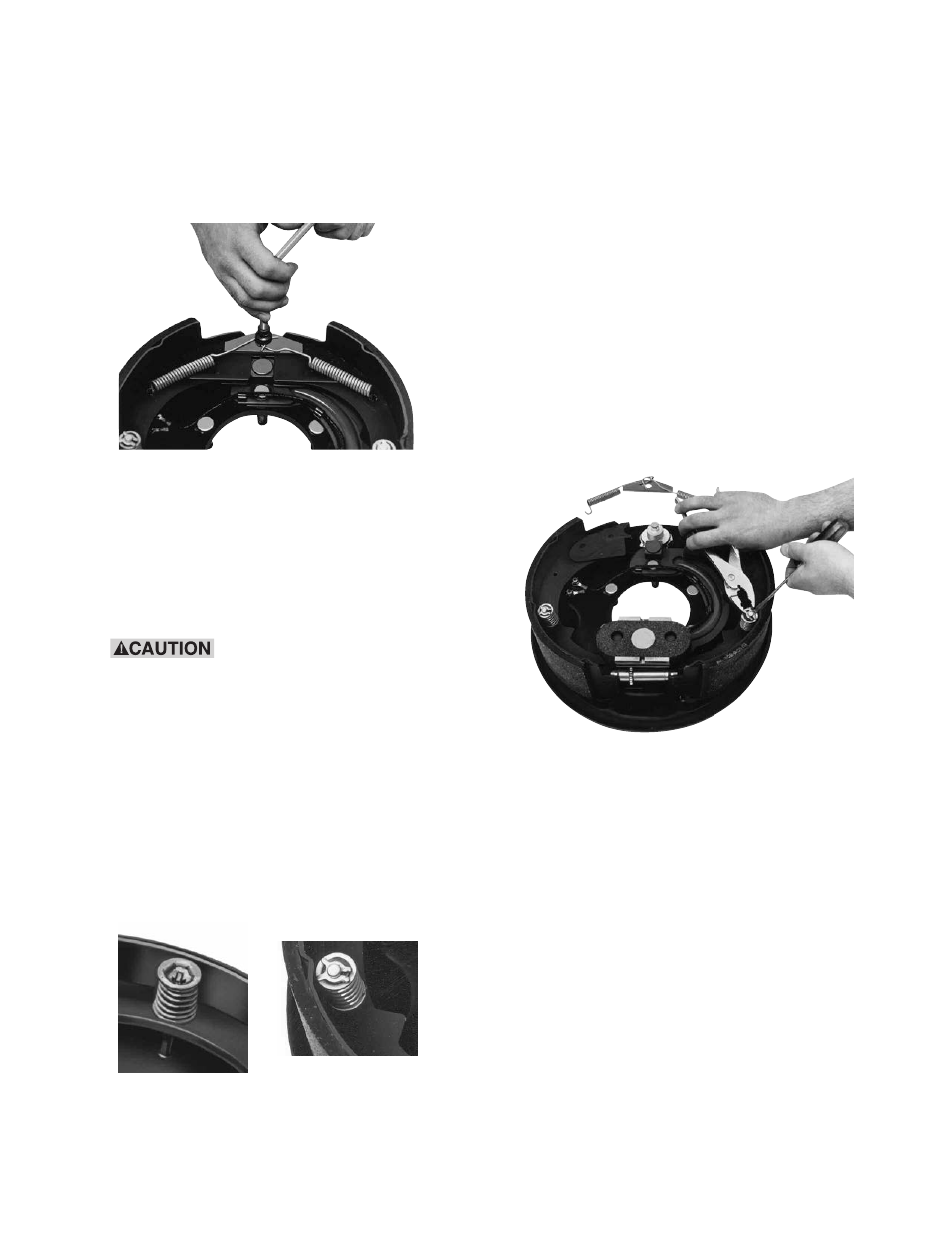
1. Remove the two shoe returns springs (4-1)
with a brake spring tool. (See Figure 29).
2. Remove the anchor pin plate (4-2).
3. Remove the two shoe hold down spring
assemblies (2-2, 2-3, 2-4, 2-5, and 2-6).
There are two assembly configurations.
Follow the instructions for either Style A or
Style B.
These assemblies are spring
loaded. Wear safety glasses while
performing these operations, and keep
your head away from the parts being
removed. Follow the instructions
carefully.
Style A (old style): Style A uses a slotted,
dished washer with a swaged pin to lock
the spring assembly in place. (See Figure
30).
Depress the washer/spring assembly and
Figure 30 - Removing Shoe Hold Down
Assemblies (Style A)
Figure 29 - Remove Shoe Return Springs
rotate the top washer 90°.
Slowly relax the spring and disassemble.
Style B: Style B uses an “X” washer retainer
(2-6) to lock the spring assembly in place.
The “X” washer retainer should only be
used once. If it is removed during repairs,
discard it and use the new ones provided in
the kit.
Depress the spring assembly, and using a
pliers, squeeze the ears of the “X” washer
retainer together to open it.
Then relax the spring assembly and remove
it, being sure to discard the old “X” washer
retainer. (2-6). (See Figure 31).
4. Remove the two shoes (2-1), the adjuster
(3-1, 3-2, and 3-3) and the adjuster spring
(3-5) as an assembly by spreading the
shoes apart at the top and lifting off.
Disassemble and discard the old adjuster
(3-1, 3-2, and 3-3) and the old adjuster
spring (3-5).
5. Lubricate the six shoe pads on the backing
plate with “moly” impregnated grease. (See
Figure 32).
Figure 31 - Removing Style B Shoe Hold
Down Assemblies
(Style A)
(Style B)