Warner Electric Electric Wheel Brake 12-1_4 x 3-1_2 Replacement User Manual
Page 10
10
Warner Electric • 800-825-9050
819-0209
during the disassembly (Step 4).
Route the magnet lead wires individually
through the five clips on the arm, duplicat-
ing the routing noted in Step 4. (See Figure
21).
On right-hand brakes allow 2-3/8-inches of
wire between the magnet and the first clip.
(See Figure 22).
On left-hand brakes allow 3-1/8-inches of
wire between the magnet and the first clip.
(See Figure 22 A).
Allowing this much wire prevents strain on
the wires when the magnet is pulled out
the maximum distance.
11. Assemble magnet lead wire terminals onto
terminal posts (6-3) in the following
sequence:
a. Place one internal lockwasher over each
post.
b. Place one wire terminal over each post.
c. Place one internal nut (6-1) over each
post and tighten them to 30-40 in. lbs.
torque.
12. Close the shoe (2-1) that was spread to
expose the terminal and install the anchor
pin plate (4-2).
13. Install the shoe return springs (4-1), using a
brake spring tool.
14. Move the magnet lever arm along its track
to insure that the shoes expand and con-
tract properly and are in the correct
adjustment. When making this test, the
shoes can stick in their expanded posi-
tion. To correct this, merely push the shoe
back into position. Once the shoe drum
has been installed, the shoe will be
restricted from expanding far enough to
stick.
15. Reassemble the drum and wheel. Make
sure wheel bearings and wheel nuts are
adjusted to axle manufacturer’s specifica-
tions.
Replacing Shoes and Linings/Shoe Hold
Down Springs
Kit No. 1301-100-005
See Page 3 for kit description
Note: Shoes are interchangeable so there
is no concern regarding right or left hand
during assembly. Brake drums must be
resurfaced or replaced when brake shoes
are replaced to assure proper break-in and
performance.
Brakes must be road tested and new lin-
ings worn in after installation. See “Road
Test and Burnish Procedure,” page 25.
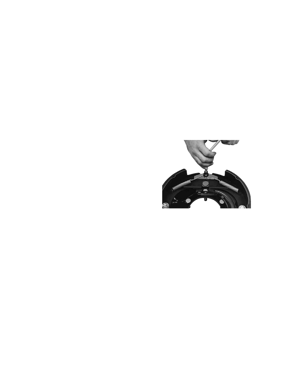
1. Remove the two shoe return springs (4-1)
using a brake spring tool. (See Figure 23).
2. Remove the anchor pin plate (4-2).
Figure 23 - Removing Shoe Return Springs