Warner Electric Electric Wheel Brake 12-1_4 x 3-1_2 Replacement User Manual
Page 5
5
Warner Electric • 800-825-9050
819-0209
Note: Wire guide spring is used only when
replacing single magnet on old style magnet
lever arm. (Figure 5).
Brakes must be road tested and new mag-
net(s) must be burnished after installation.
See “Road Test and Burnish Procedure,”
page 25.
Case I: Replacing Single Magnet on New
Style Magnet Arm with New Single Magnet
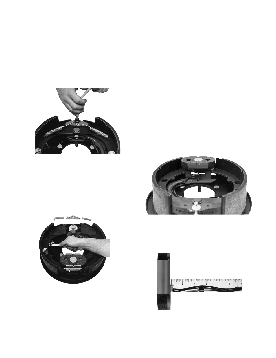
1. Remove the two shoe return springs (4-1),
using a brake spring tool. (See Figure 6).
2. Remove the anchor pin plate (4-2) and
spread the shoe (2-1) apart, exposing the
brake terminal (6).
3. Remove the two internal nuts (6-1) which
secure the magnet lead wires to the terminal
posts (6-3). (See Figure 7).
4. Note wire routing on magnet lever arm (5-1).
Mark the exact position of the wire clips (1-2)
with a grease pencil, and remove the lead
wires from the clips on the arm. Leave the
clips in place.
5. Remove the used magnet (1-1) from the lever
arm (5-1) and discard magnet.
6. Replace the used magnet springs (1-3) with
new ones provided. Note small diameter end
of springs set on the magnet lever arm (5-1).
7. With the magnet lever arm (5-1) positioned so
the square cam is away from you, install the
new single magnet on the pins so that the
wires are located at the upper right hand side
of the magnet. (The label on the new magnet
also explains the magnet mounting method).
8. Replace the five old wire clips (1-2) on the
magnet lever arm (5-1) with new clips. Install
the clips in the same location as marked dur-
ing disassembly (Step 4).
Route the magnet lead wires individually
Figure 7 - Removing Internal Nuts
Figure 6 - Removing Shoe Return Springs
Figure 8 - Wire Routing and Magnet Position
Figure 9 - R.H. Brakes