Warner Electric Electric Wheel Brake 12-1_4 x 3-1_2 Replacement User Manual
Page 12
12
Warner Electric • 800-825-9050
819-0209
5. Note: This step pertains only to brakes
using Style “A” shoe hold down assem-
blies.
Discard all old pins, rubber washers, spring
cups, and old springs. Drill out the two hold
down pin clearance holes in the backing
plate with a 5/16-inch (.312-inch) dia. drill.
6. Lubricate the six shoe pads on the backing
plate with “moly” impregnated grease. (See
Figure 26).
7. Assemble the two new shoes (2-1), adjuster
spring (3-5), and adjuster (3-1, 3-2, and 3-
3). Make sure the adjuster is fitted into the
notches in the shoe web. Install the assem-
bly onto the brake. (See Figure 27).
8.
To facilitate the installation of the new style
shoe hold down assemblies, rotate either
shoe (2-1) away from the anchor pin so that
the shoe slides off the shoe pad and onto
the curl of the backing plate. This proce-
dure will minimize the hold down spring
compression required.
9.
Insert a hold down pin (2-3) through the
hole in the rear of the backing plate and the
hole in the shoe (2-1) web. Hold pin in
place.
10. Place a spring cup (2-4), convex upward,
over the pin. Next install the spring (2-2), a
spring cub (2-4) (convex downward), and
then a spherical washer (2-5) (it nests in the
spring cup) over the protruding pin (2-3).
11. Slide a new “X” washer retainer (2-6)
between the head of the pin (2-3) and the
spherical washer (2-5) while compressing
the assembly. Using pliers, close the “X”
washer retainer to lock on the pin.
12. Lift the shoe (2-1) onto the shoe pads on
the backing plate with a heavy screwdriver.
Rotate it into the place against the anchor
pin.
13. Repeat Steps 8 through 12 for the second
shoe hold down assembly.
14. Install the anchor pin plate (4-2).
15. Install the shoe return springs (4-1), using a
brake spring tool.
16. Check that the shoes expand and contract
properly. Set the shoes to the fully con-
tracted position before installing the drums.
17. Reassemble the drums and wheels. Make
sure the wheel bearings and wheel nuts are
adjusted to the axle manufacturer’s specifi-
cations.
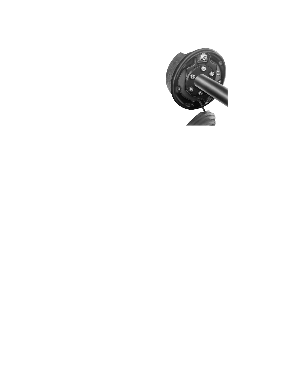
18. Brake Adjustment: Remove the rubber
adjuster plug (3-4) and insert an adjusting
tool. (See Figure 28).
With the wheel off the ground, expand the
shoes until the brake drags significantly.
(Upward motion of the tool turns the
adjusting nut, 3-3, to expand the shoes
against the drum.)
Then back off the adjuster (downward
motion) until the wheel turns freely, usually
10 to 12 notches.
After the initial 500 miles of operation
(when the new shoes and drum have been
seated), brake readjustment is recommend-
ed.
Figure 28 - Brake Adjustment