Warner Electric Electric Wheel Brake 12-1_4 x 3-1_2 Replacement User Manual
Page 22
22
Warner Electric • 800-825-9050
819-0209
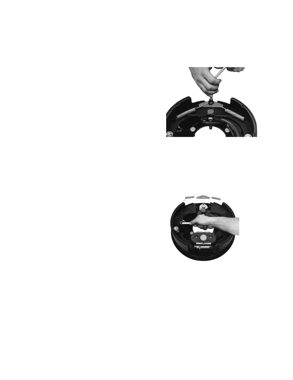
Replacing Terminal Assembly
Kit No. 1301-100-011
See page 3 for kit description
1.
Remove the two shoe return springs (4-1)
using a brake spring tool. (See Figure 52).
2.
Remove the anchor pin plate (4-2) and
spread the shoe (2-1) apart, exposing the
brake terminal (6).
3.
Remove the two internal nuts (6-1) which
secure the magnet lead wires to the terminal
posts (6-3). (See Figure 53).
4.
Turn the brake over and remove the nuts (6-
7), lockwashers (6-6), and flat washers (6-8)
from the two terminals (6). Slide the insula-
tors (6-5) off the terminal posts (6-3).
Remove the molded plastic terminal (6-4)
and posts (6-3) from the top side of the
backing plate.
Install the new hardware on the backing
plate in reverse order.
Figure 52 - Removing Shoe Return Springs
Figure 53 - Removing Internal Nuts
17. Lift the shoes (2-1) onto the shoe pads on
the backing plate with a heavy screwdriver.
Rotate them into place against the anchor
pin.
18. Install the anchor pin plate (4-2).
19. Install the shoe return springs (4-1) using a
brake spring tool
20. Move the magnet lever arm along its track
to ensure that the shoes expand and con-
tract properly and are in the correct adjust-
ment. When making this test, the shoes
can stick in their expanded position. To
correct this, merely push the shoe back
into position. Once the shoe drum has
been installed, the shoe will be restricted
from expanding far enough to stick.
21. Reassemble the drums and wheel and
make sure the wheel bearings and wheel
nuts are adjusted to the axle manufactur-
er’s specifications.