Warner Electric ER-1225 User Manual
Page 9
Warner Electric • 800-825-9050
819-0466 9
Step 5: Position the magnet/spacer assembly
on the motor pilot and align the holes
in the magnet with the spacer and
mounting surface holes . Following the
manufacturer’s instructions, apply grade
242 Loctite to the threads of each
furnished cap screw, add a lock washer,
and fasten the spacer/magnet assembly
on the motor . Tighten these screws
to 25 to 28 lb .ft . torque with a torque
wrench .
Make the electrical connection . The positive and
negative of the power lead must be connected to
the positive and negative lead wires or terminals
of the brake, respectively . follow KONE Inc .
instructions to set the release voltage of the brake .
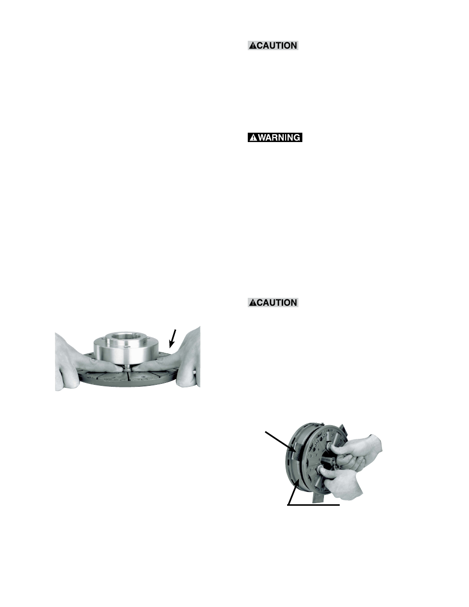
Step 6: Place the armature hub assembly on a
flat surface with the armature working
face up . Push down on each detent
cup (Item 6) with your fingers, sliding the
armature down until the armature will
move no further . (See Figure 9)
Armature
working
surface
Figure 9 - Positioning the detent cups in the
armature.
Step 7: Insert the taper-lock bushing (Item 1) into
the hub (Item 2) . Align the two half-drilled
holes in the taper-lock bushing with
the two half-threaded holes in the hub .
Insert two set screws (Item 12) into the
aligned holes and screw them in loosely
to maintain alignment during assembly .
During steps 8, 9, and 10,
handle the armature/hub assembly by the
hub (Item 2) or the drive pins (Item 4) only,
making sure the armature (Item 3) is as close
to the retainer ring (Item 10) as possible. Any
movement of the armature on the pins (Item
4) will reduce available armature travel and
may cause improper air gap setting.
Keep fingers clear of the
area between the magnet (Item 11) and the
armature (Item 3) because the armature will
be pulled sharply toward the magnet after the
gap is closed to approximately 1/8 inch. Injury
can result if fingers are pinched between the
armature and the magnet.
Step 8: Insert the key in the motor shaft keyway .
Step 9: Make sure no power is applied to
the brake. Place three steel shims 120
degrees apart on the magnet as shown
in Figure 10 .
0.062 inch shims are
recommended. Do not use shims thicker than
0.125 inch or you will shorten brake life by
reducing available armature travel.
Slip the armature hub assembly onto the motor
shaft until the armature makes contact with the
shims . Using a drift, lightly tap on the taperlock
bushing at several points around the
circumference with a small hammer until it will slide
no further onto the shaft . (See Figure 11)
Keep fingers away
from this area
Shims
Figure 10 - Armature installation with shims in
place.