Warner Electric ER-1225 User Manual
Page 13
Warner Electric • 800-825-9050
819-0466 13
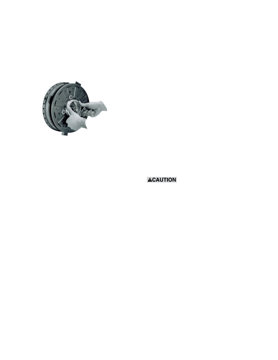
Step 9: Apply power (90 VDC) to the brake and
remove the shims . Set the airgap by
pressing the armature into contact with
the magnet and then releasing as shown
in Figure 17 . The armature should spring
back approximately 3/64 ( .045) inch
when power is applied to the magnet .
Figure 17 - Setting the airgap.
Step 10: If the brake includes temperature and
wear sensor wires, follow KONE Inc .
instructions to make proper connections .
Color coding is as follows:
Yellow wires - temperature sensor
Red wire - 90% wear sensor
Black wire - 70% wear sensor
Step 11: Burnish the brake as follows: Start and
stop the escalator 30 times . Allow 5-10
seconds delay between start and stop .
Step 12: With power off, check brake static
torque, which must be at least 125
lb .ft . excluding system drag . If less,
repeat (Step 11) . If the brake does not
meet the torque requirement after two
burnishings, replace it .
Step 13: When the armature is released and
rotating freely, the armature working face
should not rub on the magnet working
face and the armature working face axial
runout (wobble) should not exceed .015
inch . If the armature rubs or wobbles
excessively, remove the armature
assembly and reassemble it as instructed
in Steps 15-17 below . If the problem
persists, replace the brake .
Step 14: Brake installation is complete . Follow
KONE Inc . instructions to install the
remainder of the system .
Steps to disassemble the armature from
transmission shaft.
Step 15: Using socket wrench, remove bolt &
washer from the shaft end .
Step 16: Apply power and slowly slide the
armature away from magnet .
Do not pry the armature away
from the magnet. This can distort the
armature and require complete brake
replacement.
Step 17: Follow Steps 5 thru 13 .