Warner Electric ER-1225 User Manual
Page 7
Warner Electric • 800-825-9050
819-0466 7
Step 10: Using a torque wrench, tighten the hub
bushing screws (Item 12) alternately and
evenly until tight . Place a drift against
the large end of the bushing at several
points around the circumference and
tap it lightly with a small hammer . (See
Figure 5) Repeat this alternate tapping
and re-tightening until the specified
torque no longer turns the screws after
tapping . Tighten the screws to 15 lb .ft .
torque . The gap between armature
and magnet must be 0 .062 inch to
0 .125 inch . If the gap is outside of that
range, reposition the armature hub
assembly as described in Steps 11 & 12;
otherwise, go to Step 13 .
Figure 5 - Seating the taperlock bushing.
Step 11: Apply power (90 VDC) to release the
brake . Remove the taperlock bushing
and armature assembly (Items 1,2,3)
from the motor shaft . To remove
armature assembly; using a hex key
wrench, remove both set screws (Item
12) from the taperlock bushing (Item 1) .
Insert one set screw into the previously
vacant hole in the taperlock bushing
and tighten this screw until the bushing
is loosened in the hub (Item 2) . If the
bushing does not loosen, tap on the
hub with a plastic hammer .
Do not pry the armature
away from the magnet. This can distort
the armature and require complete brake
replacement.
Step 12: Repeat Steps 6 ,7 , 8, 9, and 10 .
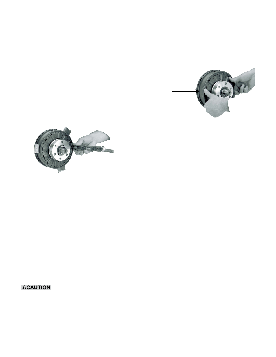
Step 13: Apply power (90 VDC) to the brake and
remove the shims . Set the airgap by
pressing the armature into contact with
the magnet and then releasing as shown
in Figure 6 . The armature should spring
back approximately 3/64 ( .045) inch .
Keep fingers
away from
this area
Figure 6 - Setting the airgap
Step 14: If the brake includes temperature and
wear sensor wires, follow KONE Inc .
instructions to make proper connections .
Color coding is as follows:
Yellow wires - temperature sensor
Red wire - 90% wear sensor
Black wire - 70% wear sensor
Step 15: Burnish the brake as follows: Start and
stop the escalator 30 times .
Step 16: With power off, check brake static
torque, which must be at least 125 lb .ft .
excluding systems drag . If less, repeat
Step 15 . If the brake does not meet the
torque requirement after two burnishings,
replace it .
Step 17: When the armature is released and
rotating freely, the armature working face
should not rub on the magnet working
face and the armature working face
axial runout (wobble) should not exceed
.015 inch . Additionally, if the armature
rubs or wobbles excessively, remove
the armature assembly and reassemble
it as instructed in Steps 11 & 12 . If the
problem persists, replace the brake .