Sfc-1000 clutch coupling bearing mounted, How to order, Example – Warner Electric SFC-1525 User Manual
Page 21
21
Warner Electric • 800-825-9050
P-207
•
819-0516
1
2
3
4-1
4-2
4-3
4-4
4-5
4
(Shipped Assembled)
4-6
6
7
5-5
5-4
5-3
5-10
5-9
5-2
5
(Shipped Assembled)
5-7
5-8
5-1
5-6
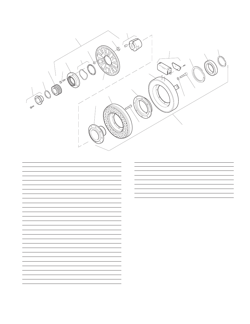
SFC-1000 Clutch Coupling Bearing Mounted
Item Description Part Number Qty.
1 Bushing* 1
3/4" to 2-11/16" Bore 180-0026 to 180-0057
2 Retainer Ring 748-0007 1
3 Splined Hub 540-0062 1
4 Armature & Splined Adapter 5202-111-001 1
4-1 Capscrew 797-0341 3
4-2 Splined Adapter 104-0009 1
4-3 Autogap Accessory 5322-101-004 1
4-4 Spacer 748-0333 3
4-5 Armature 5322-111-036 1
4-6 Locknut 661-0004 3
5 Field & Rotor Assembly 1
6 Volt 5202-452-012
24 Volt 5202-452-014
90 Volt 5202-452-015
5-1 Rotor 1
Standard Friction Material 5202-751-003
Optional LK Facing 5202-751-007
5-2 Field 1
6 Volt 5202-451-040
24 Volt 5202-451-042
90 Volt 5202-451-043
5-3 Retainer Ring 748-0116 1
5-4 Ball Bearing 166-1046 1
5-5 Retainer Ring 748-0582 1
5-6 Rotor Hub 540-1300 1
5-7 Buttonhead Capscrew 797-1261 6
Item Description Part Number Qty.
5-8 Ring Adapter 748-1047 1
5-9 Lockwasher 950-0359 6
5-10 Socket Head Capscrew 797-0422 6
6 Bushing* 1
1/2" to 2" Bore 180-0155 to 180-0179
7 Conduit Box 5200-101-012 1
*For specific part numbers see page 28.
How to Order:
1. Specify Bore Size for Items 1 and 6.
2. Specify Voltage for Item 5.
Example:
SFC-1000 Clutch Coupling per I-25598 - 90 Volt, 1"
Bore
These units, when used in conjunction with the correct
Warner Electric conduit box, meet the standards of
UL508 and are listed under guide card #NMTR, file
#59164.