Warner Electric SFC-1525 User Manual
Page 2
2
Warner Electric • 800-825-9050
P-207
•
819-0516
The illustration drawings, parts lists, and exploded views
for these units can be found beginning on page 8.
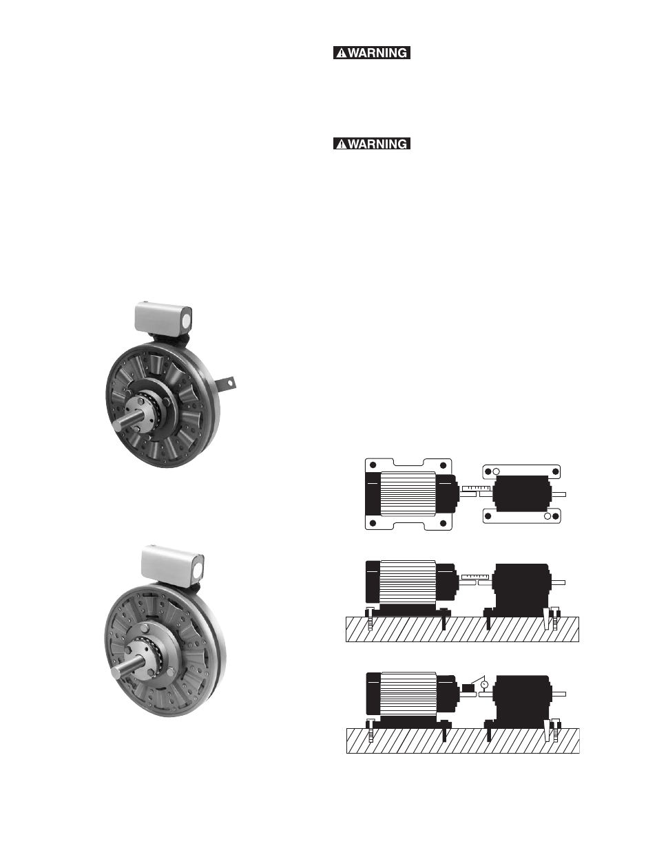
A. Aligning the Shafts
In order for the clutch-coupling unit to operate
properly, the mounting shafts of the motor and
reducer or other hardware must be aligned with
respect to each other before the unit is installed.
The two shafts should be con cen tric with each other
within .006 T.I.R., and angular alignment should be
within 1/2 degree. (See to Figure 1)
Contents
Installation Instructions . . . . . . . . . . . . . . . . . . . . . . . .2
SFC-825, SFC-1000, SFC-1225, SFC-1525 and
SFC-1525 Hi-Torque
Torque Tabs . . . . . . . . . . . . . . . . . . . . . . . . . . . . . . . .5
Electrical Coil Data . . . . . . . . . . . . . . . . . . . . . . . . . . .6
Burnishing and Maintenance . . . . . . . . . . . . . . . . . . . .6
Illustration Drawings
SFC-825, SFC-1000 Flange Mounted . . . . . . . . . . .8
SFC-1225, SFC-1525 and SFC-1525
Hi-Torque Flange Mounted . . . . . . . . . . . . . . . . . . .12
SFC-825, SFC-1000 Bearing Mounted . . . . . . . . .18
SFC-1225, SFC-1525 Bearing Mounted . . . . . . . .22
Bushing Part Numbers . . . . . . . . . . . . . . . . . . . . . . .28
Warranty . . . . . . . . . . . . . . . . . . . . . . . . . . .Back Cover
Follow the installation instructions
in this manual care ful ly to ensure safe, reliable
operation. All stated or implied manufacturer
warranties are voided if this product is not installed
in accordance with these in struc tions.
SFC-825
Flange Mounted
SFC-825
Bearing Mounted
Clutch-Coupling Spline Drive Armatures
SFC-825 SFC-1000 SFC-1225 SFC-1525
SFC-1525 Hi-Torque
Figure 1
Failure to follow these instruc-
tions may result in product damage, equipment
damage, and serious or fatal injury to personnel.