How to order, Example – Warner Electric SFC-1525 User Manual
Page 13
13
Warner Electric • 800-825-9050
P-207
•
819-0516
1
2
3
4-2
4-3
4
(Shipped Assembled)
4-4
4-1
4-5
4-6
9A
10A
7
6
5
8
10B
9B
11
11
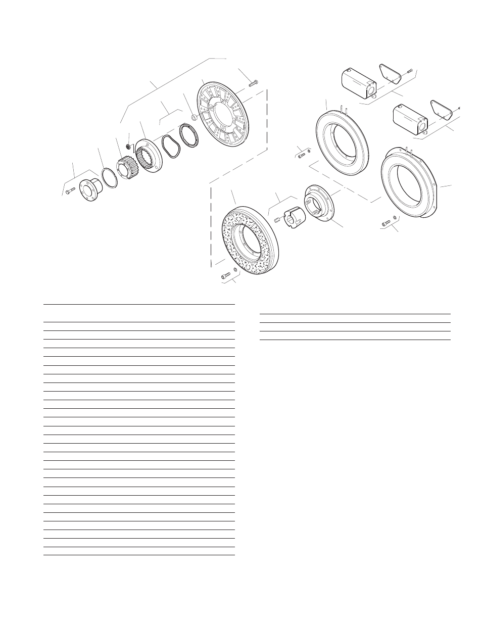
SFC-1225 Clutch Coupling Flange Mounted Inside Mtd. Outside Mtd.
SFC-1225
Item Description Part Number Qty.
1 Bushing*
3/4" to 2-11/16" Bore 180-0026 to 180-0057 1
2 Retainer Ring 748-0005 1
3 Splined Hub 540-0064 1
4 Armature & Splined Adapter 5203-111-001 1
4-1 Locknut 661-0005 4
4-2 Splined Adapter 104-0010 1
4-3 Autogap Accessory 5323-101-002 1
4-4 Spacer 266-0004 4
4-5 Armature 5323-111-034 1
4-6 Screw 797-0356 4
5 Mounting Accessory 5321-101-002 2
6 Rotor 1
Standard Friction Material 5203-751-001
Optional LK Facing 5203-751-004
7 Bushing*
1/2" to 2-1/2" Bore 180-0185 to 180-0217 1
8 Rotor Hub 540-0318 1
9A Field - Inside Mounted 1
6 Volt 5203-451-002
24 Volt 5203-451-006
90 Volt 5203-451-005
9B Field - Outside Mounted 1
6 Volt 5203-451-010
24 Volt 5203-451-013
90 Volt 5203-451-011
SFC-1225
Item Description Part Number Qty.
10A Mounting Accessory - I.M. 5321-101-001 1
10B Mounting Accessory - O.M. 5321-101-002 2
11 Conduit Box 5200-101-012 1
*See page 28 for specific part numbers.
How to Order:
1. Specify Bore Size for Item 1.
2. Specify Bore Size for Item 7.
3. Specify Voltage for Item 9A or 9B.
4. Specify Inside or Outside Mounted for Item 5.
5. Specify Inside Mounted for Items 9A and 10A or
Outside Mounted for Items 9B and 10B.
Example:
SFC-1225 Clutch Coupling per
I-25604 - 90 Volt, Inside Mounted,
1-1/2" Bore (Item 1), 1-3/4" Bore (Item 7).
These units, when used in conjunction with the correct
Warner Electric conduit box, meet the standards of
UL508 and are listed under guide card #NMTR, file
#59164.