Customer shall maintain – Warner Electric SFC-1525 User Manual
Page 10
10
Warner Electric • 800-825-9050
P-207
•
819-0516
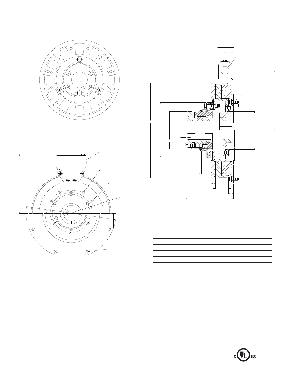
SFC-1000 Clutch Coupling Flange Mounted
Drawing I-25584
Arm Shaft
.750 – 2.687
Rotor Shaft
.500 – 2.000
Static Torque
240 lb. ft.
Maximum Speed
3,600 rpm
Standard Voltage
D.C. 6, 24, 90
All dimensions are nominal unless otherwise noted.
See page 28 for details
on Bushings.
Armature View
Field View
(Inside & Outside Mounted)
3.750
7.687 MAX
Removeable plug in ends
for 1/2” conduit
.358/.388 dia. (6) holes equally
spaced on a6.125 dia. *
.350/.341 dia. (6) holes
equally spaced on 4.875 dia.**
5.378/5.376
Pilot Dia.
11.500/11.498
Pilot Dia.
.358/.338 dia *(8) holes equally
spaced on 10.625 dia.*
Customer Shall Maintain:
1. Concentricity of field mounting pilot diameter with
rotor mounting shaft within .006 T.I.R.
2. Squareness of field mounting face with rotor shaft
within .006 T.I.R. mea sured at field mounting bolt
circle.
3. Rotor mounting shaft concentric with ar ma ture
mounting shaft within .006 T.I.R.
4. Angular alignment of shafts within 1/2 degree.
* Mounting holes are within .010 of true po si tion relative to pilot
diameter.
** Mounting holes are within .008 of true po si tion relative to pilot
diameter.
Note: The two mating shafts on which the clutch is
mounted must be mounted rigidly to prevent
flexing during engagement. Any flexing will cause
vibration and rapid clutchwear. The drive motor
should not be mounted on the reducer "scoop"
mount or other flexible mounts.
1.560
Ø4.127
±.001
1.250
.250
.562 MAX
.093
.562
1.375
5/16-18 UNC-3A
6.531
Ø10.328
MAX
HOLE FOR 1/2" CONDUIT
(EACH END)
.500
.910 MAX
5.359 MAX
.062
.234
2.500
2.688
Ш4.094
Ш6.000
PILOT