Example – Warner Electric SFC-1525 User Manual
Page 19
19
Warner Electric • 800-825-9050
P-207
•
819-0516
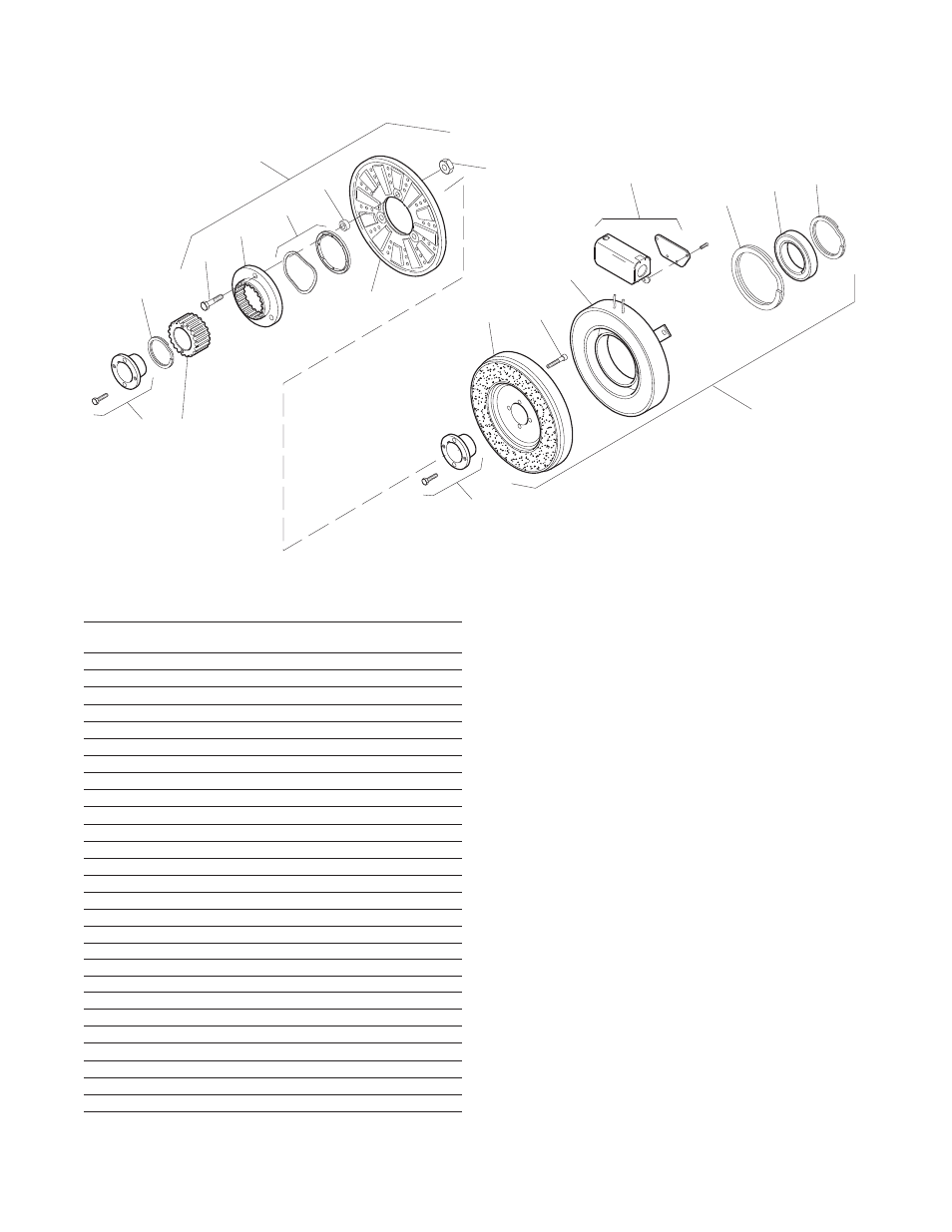
1
3
2
4-1
4-2
4-3
4
(Shipped Assembled)
4-4
4-6
4-5
1
5-1
5-2
5-3
6
5-3-2
5-4
5
(Shipped Assembled)
5-3-1
SFC-825 Clutch Coupling Bearing Mounted
How to Order:
1. Specify Bore Size for Item 1 (both shafts).
2. Specify Voltage for Item 5.
Example:
SFC-825 Clutch Coupling per I-25574 - 90 Volt, 1" Bore
These units, when used in conjunction with the correct
Warner Electric conduit box, meet the standards of
UL508 and are listed under guide card #NMTR, file
#59164.
SF-825, B.M.
Item Description Part Number Qty.
1 Bushing* 2
1/2" to 1-1/2" Bore 180-0002 to 180-0018
2 Retainer Ring 748-0006 1
3 Splined Hub 540-0057 1
4 Armature & Splined Adapter 5201-111-001 1
4-1 Capscrew 797-0341 3
4-2 Splined Adapter 104-0008 1
4-3 Autogap Accessory 5321-101-006 1
4-4 Spacer 748-0333 3
4-5 Armature 5321-111-022 1
4-6 Locknut 661-0004 3
5 Field & Rotor Assembly 1
6 Volt 5201-452-002
24 Volt 5201-452-004
90 Volt 5201-452-006
5-1 Rotor 1
Standard Friction Material 5201-751-008
Optional LK Facing 5201-751-014
5-2 Mounting Accessory 5201-101-005 1
5-3 Field and Bearing Assembly 1
6 Volt 5201-451-054
24 Volt 5201-451-056
90 Volt 5201-451-057
5-3-1 Bearing 166-0412
5-3-2 Retainer Ring 748-0111
5-4 Retainer Ring 748-0016 1
6 Conduit Box 5200-101-012 1
*See page 28 for specific part numbers.