Customer shall maintain, When hub is furnished by customer – Warner Electric SFC-1525 User Manual
Page 14
14
Warner Electric • 800-825-9050
P-207
•
819-0516
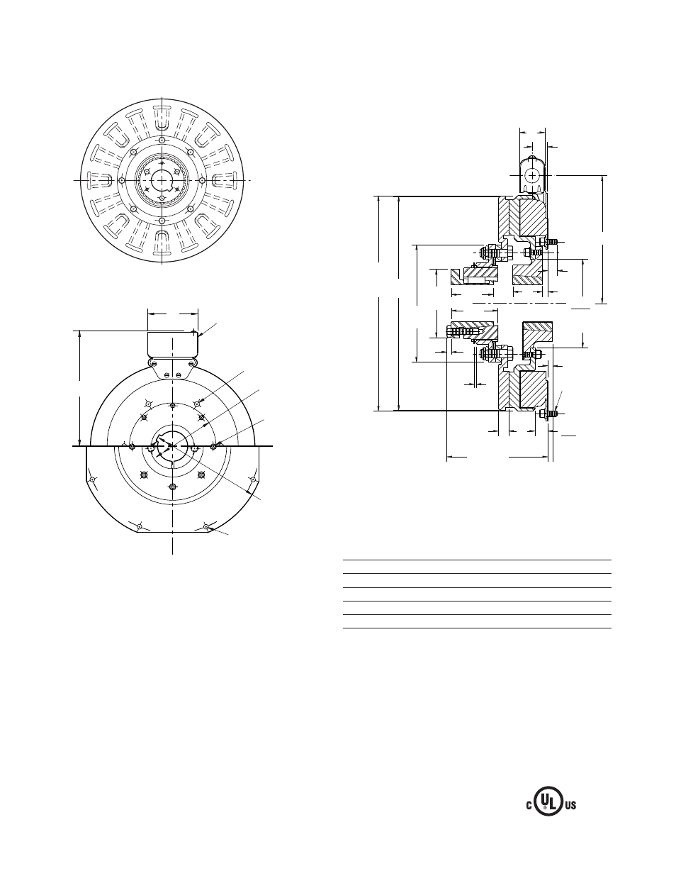
SFC-1525 Clutch Coupling Flange Mounted
Drawing I-25630
Armature View
Arm Shaft
.750 – 2.687
Rotor Shaft
.937 – 3.000
Static Torque
700 lb. ft.
Maximum Speed
2,000 rpm
Standard Voltage
D.C. 6, 24, 90
All dimensions are nominal unless otherwise noted.
Field View
(Inside & Outside Mounted)
Removable plug in ends for
1/2" conduit.
.350/.341 dia. (8)
holes equally
spaced on 8.500
dia.**
.358/.338 dia. (12) holes
equally spaced on 16.000
dia.*
9.002/9.000
Pilot Dia.
16.875/16.871
Pilot Dia.
3.750
10.343 Max.
.358/.338 dia. (12) holes
equally spaced on 9.750
dia.*
See page 28 for de tails
on Bush ings.
.234
.562
.437
.758
.742
1.562
.062
.562
2
.218
5/16-18
UNC-3A
9.187
.921
1.546
15.671
Max.
Dia. 15.578
Dia.
8.750
Dia.
4.093
Dia.
2.500
2.687
7.878
7.876
Pilot
Dia.
6.031 Max.
* Mounting holes are within .010 of true position relative to pilot
diameter.
** Mounting holes are within .008 of true position relative to pilot
diameter.
Customer Shall Maintain:
1. Concentricity of field mounting pilot diameter with
rotor mounting shaft within .006 T.I.R.
2. Squareness of field mounting face with rotor
mounting shaft within .006 T.I.R. measured at field
mounting bolt circle.
3. Rotor mounting shaft concentric with armature
mounting shaft within .006 T.I.R.
4. Angular alignment of shafts within 1/2 degree.
When Hub is Furnished by Customer:
Rotor mounting pilot diameter must be concentric with
rotor mounting shaft within .006 T.I.R.